
AMC 20-158A Aircraft electrical and electronic system high-intensity radiated fields (HIRF) protection
ED Decision 2022/001/R
1. PURPOSE
a. This AMC describes an acceptable means, but not the only means, for demonstrating compliance with the applicable certification specifications (CSs) related to high-intensity radiated fields (HIRF) protection (CS 23.1308, 25.1317, 27.1317, and 29.1317). Compliance with this AMC is not mandatory, and an applicant may elect to use an alternative means of compliance. However, the alternative means of compliance must meet the relevant requirements, ensure an equivalent level of safety, and be approved by EASA on a product or ETSO article basis.
b. The modal verb ‘must’ is used to indicate which means are necessary to demonstrate compliance with the applicable CSs by using this AMC. The modal verb ‘should’ is used when following the AMC to indicate that an action is recommended but is not necessary to demonstrate compliance with the applicable CSs when using this AMC.
2. SCOPE AND APPLICABILITY
This AMC provides possible means to demonstrate compliance with CS 23.1308/23.2520, 25.1317, 27.1317, and 29.1317 for the effects of HIRFs. This AMC may be used by applicants for a new type certificate (TC) or a change to an existing TC when the certification basis requires to address the above-mentioned CSs.
Note: For CS-23 Amendment 5 and higher, a new HIRF specification, i.e. CS 23.2520, which differs from the previous CS 23.1308, is included. The associated AMC to CS 23.2520 are published separately in the AMC & GM to CS-23, based on ASTM F3061 / F3061M-17 and F3236-17. This AMC could nevertheless be used as guidance for demonstrating compliance with CS 23.2520.
3. DOCUMENT HISTORY
This AMC supersedes AMC 20-158, Aircraft Electrical and Electronic System High-Intensity Radiated Fields (HIRF) Protection, dated 15 July 2015.
4. RELATED MATERIAL
a. European Union Aviation Safety Agency (EASA) (in this document also referred to as ‘the Agency’)
Certification Specifications:
1. CS 23.1308, CS 25.1317, CS 27.1317, and CS 29.1317, High-intensity Radiated Fields (HIRF) Protection;
2. CS 23.1309, CS 25.1309, CS 27.1309, and CS 29.1309, Equipment, systems, and installations; and
3. CS 23.1529, CS 25.1529, CS 27.1529, and CS 29.1529, Instructions for Continued Airworthiness.
EASA Certification Specifications (CSs) and Acceptable Means of Compliance (AMC) may be downloaded from the EASA website at www.easa.europa.eu.
b. FAA Advisory Circulars (ACs)
1. AC 23.1309-1E, System Safety Analysis and Assessment for Part 23 Airplanes;
2. AC 25.1309-1A, System Design and Analysis;
3. AC-27-1B, Certification of Normal Category Rotorcraft;
4. AC-29-2C, Certification of Transport Category Rotorcraft, or later revisions;
5. AC 20-158A, The Certification of Aircraft Electrical and Electronic Systems for Operation in the High‑Intensity Radiated Fields (HIRF) Environment.
Applicants can view and download copies from the web-based FAA Regulatory and Guidance Library (RGL) at www.airweb.faa.gov. On the RGL website, the applicant should select ‘Advisory Circular’, then select ‘By Number’. ACs are also available on the FAA website at http://www.faa.gov/regulations_policies/advisory_circulars/.
c. European Organisation for Civil Aviation Equipment (EUROCAE)
Copies of these documents can be requested from EUROCAE, 102 rue Etienne Dolet, 92240 Malakoff, France; Telephone: +33 1 40 92 79 30; Fax: +33 1 46 55 62 65; Website: http://www.eurocae.net.
1. EUROCAE ED-107A, Guide to certification of Aircraft in a High Intensity Radiated Field (HIRF) Environment;
2. EUROCAE ED-14G, Environmental Conditions and Test Procedures for Airborne Equipment;
3. EUROCAE ED-79A, Guidelines for Development of Civil Aircraft and Systems;
4. EUROCAE ED-234, User Guide Supplement to EUROCAE ED-14G.
EUROCAE documents may be purchased from:
European Organisation for Civil Aviation Equipment
9-23 rue Paul Lafargue
"Le Triangle" building
93200 Saint-Denis, France
Telephone: +33 1 49 46 19 65
(Email: eurocae [at] eurocae.net (eurocae[at]eurocae[dot]net), website: www.eurocae.net
d. Radio Technical Commission for Aeronautics (RTCA)
RTCA/DO-160G, Environmental Conditions and Test Procedures for Airborne Equipment. This document is technically equivalent to EUROCAE ED-14G.
RTCA documents may be purchased from:
RTCA, Inc., 1150 18th Street NW, Suite 910, Washington D.C. 20036, USA
(Email: info [at] rtca.org (info[at]rtca[dot]org), website: www.rtca.org
e. Society of Automotive Engineers (SAE International)
1. SAE Aerospace Recommended Practice (ARP) 5583A, Guide to Certification of Aircraft in a High Intensity Radiated Field (HIRF) Environment. SAE ARP 5583A and ED-107A are technically equivalent and either document may serve as the ‘User’s Guide’ referred to in this AMC.
2. SAE ARP 4754A, Guidelines For Development Of Civil Aircraft And Systems, dated December 2010. This document is technically equivalent to EUROCAE ED-79A.
3. SAE ARP 4761, Guidelines and Methods for Conducting the Safety Assessment Process on Civil Airborne Systems and Equipment, dated December 1996.
SAE International documents may be purchased from:
SAE Customer Service
400 Commonwealth Drive
Warrendale, PA
15096-0001, USA
Website: http://www.sae.org
5. BACKGROUND
a. Aircraft protection. The need for the protection of aircraft electrical and electronic systems has increased substantially in recent years for the following reasons:
1. greater dependence on electrical and electronic systems performing functions required for continued safe flight and landing of an aircraft;
2. the reduced electromagnetic shielding afforded by some composite materials used in aircraft designs;
3. the increased susceptibility of electrical and electronic systems to HIRF because of increased data bus and processor operating speeds, higher-density integrated circuits and cards, and greater sensitivities of electronic equipment;
4. expanded frequency usage, especially above 1 gigahertz (GHz)
5. the increased severity of the HIRF environment because of an increase in the number and radiated power of radio frequency (RF) transmitters; and
6. the adverse effects experienced by some aircraft when exposed to HIRF.
b. HIRF environment. The electromagnetic HIRF environment exists because of the transmission of electromagnetic RF energy from radar, radio, television, and other ground-based, shipborne, or airborne RF transmitters. The User’s Guide (SAE ARP 5583A / EUROCAE ED-107A) provides a detailed description of the derivation of these HIRF environments.
6. APPROACHES TO COMPLIANCE
a. General. The following activities should be elements of a proper HIRF certification programme. Adherence to the sequence shown is not necessary. More detailed information on HIRF certification compliance is provided in the User’s Guide (ED-107A).
The applicant should:
1. identify the systems to be assessed;
2. establish the applicable aircraft external HIRF environment;
3. establish the test environment for installed systems;
4. apply the appropriate method of HIRF compliance verification;
5. verify the effectiveness of the HIRF protection; and
6. take corrective measures (if needed).
More detailed information on these activities is proposed in Sections 7 and 8 of this AMC.
b. Identify the systems to be assessed
1. General. The applicant should identify the aircraft systems requiring a HIRF safety assessment. The applicant should define the elements of the system performing a function, considering similar and/or dissimilar redundant channels that make up the system. The process used for identifying these systems should be similar to the process for demonstrating compliance with CS 23.1309, 25.1309, 27.1309, and 29.1309, as applicable. These paragraphs address any system failure that may cause or contribute to an effect on the safety of flight of an aircraft. The effects of a HIRF encounter should be assessed to determine the degree to which the safety of the aircraft and its systems may be affected.
The operation of the aircraft systems should be assessed separately and in combination with, or in relation to, other systems. This assessment should cover:
(a) all normal aircraft operating modes, phases of flight, and operating conditions;
(b) all HIRF-related failure conditions and their subsequent effects on aircraft operations and the flight crew; and
2. HIRF safety assessment. A safety assessment related to HIRF must be performed to establish and classify the equipment or system failure condition. Table 1 provides the corresponding failure condition classification and system HIRF certification level (HCL) for the appropriate HIRF requirements. The failure condition classifications and terms used in this AMC are similar to those used in AC 23.1309-1E, AMC 25.1309, AC-27-1B, and AC-29-2C, as applicable. Only those systems identified as performing or contributing to functions whose failure would result in catastrophic, hazardous, or major failure conditions are subject to HIRF requirements. Based on the safety classification of the failure condition classification by the safety assessment, the systems should be assigned appropriate HCLs, as shown in Table 1. The HIRF safety assessment should consider the common-cause effects of HIRF, particularly for highly integrated systems and systems with redundant elements. The HIRF safety assessment determines the consequences of failures for the aircraft functions that are performed by the system. The system HCL classification assigned to the systems and functions can be different from the development assurance level (ED-79A) or the design assurance level (ED-80) assigned for equipment redundancy, software, and airborne electronic hardware (AEH). This is because HIRF is an environment that can cause common-cause effects. The term ‘DAL’ should not be used to describe the system HCL because of the potential differences in assigned classifications for software, AEH, and equipment redundancy. The HIRF safety assessment must include all electrical and electronic equipment, components and electrical interconnections, assuming that they are potentially affected by HIRF. It is not appropriate to use the HIRF immunity data for electrical and electronic equipment, components and electrical interconnections as information input for the HIRF safety assessment. This information should only be used in the next phase, to show compliance with the applicable subpart of the HIRF requirements, after the required HCL for the system is defined by the HIRF safety assessment. The HIRF safety assessment must have input and be coordinated between the safety specialist, the system specialist, and the HIRF/lightning specialist. This process may vary from applicant to applicant. Further guidance on performing the safety assessment can be found in AC 23.1309-1E, AMC 25.1309, AC-27-1B, AC-29-2C, SAE ARP 4754A / EUROCAE ED-79A, SAE ARP 4761, and ARP 5583A / EUROCAE ED‑107A.
Note: Considering that HIRF and lightning environments may have similar effects on electro‑electronic systems (disturbing electrical signals, causing upsets or damage to circuits), and that the applicable certification specifications are similarly structured, in many cases the system HCL and corresponding LCL (see AMC 20-136A) should be the same.
![]()
![]()
![]()
![]()
![]()
Table 1: HIRF most severe failure conditions of the function and system HIRF certification levels
|
HIRF REQUIREMENTS EXCERPTS FROM CS 23.1308, CS 25.1317, CS 27.1317, AND CS 29.1317
|
|
MOST SEVERE FAILURE CONDITION OF THE FUNCTION |
|
SYSTEM HIRF CERTIFICATION LEVEL (HCL) |
|
|
|
|||
|
|
|
|||
|
|
|
|||
|
|
|
|
|
|
|
(a) Each electrical and electronic system that performs a function whose failure would prevent the continued safe flight and landing of the aircraft. |
|
Catastrophic
|
|
A
|
|
|
|
|||
|
|
|
|||
|
|
|
|
||
|
|
|
|
|
|
|
(b) Each electrical and electronic system that performs a function whose failure would significantly reduce the capability of the aircraft or the ability of the flight crew to respond to an adverse operating condition. |
|
Hazardous
|
|
B
|
|
|
|
|||
|
|
|
|||
|
|
|
|||
|
|
|
|||
|
|
|
|
||
|
|
|
|
|
|
|
|
|
|
|
|
|
(c) Each electrical and electronic system that performs a function whose failure would reduce the capability of the aircraft or the ability of the flight crew to respond to an adverse operating condition. |
|
Major
|
|
C
|
|
|
|
|||
|
|
|
|||
|
|
|
|||
|
|
|
|
|
|
3. Level A systems. The specifications in CS 23.1308(a), 25.1317(a), 27.1317(a), and 29.1317(a) address adverse effects on the aircraft functions and systems that perform functions whose failure would prevent the continued safe flight and landing of the aircraft. When demonstrating compliance with CS 23.1308(a), 25.1317(a), 27.1317(a), and 29.1317(a), the electrical and electronic system is the one required to perform the function whose failure would prevent continued safe flight and landing. This electrical and electronic system must also automatically recover normal operation of the Level A functions in a timely manner to comply with CS 23.1308(a)(2), 25.1317(a)(2), 27.1317(a)(2), and 29.1317(a)(2). If all equipment and components of the system required for the normal operation of the Level A functions are not susceptible when complying with paragraphs (a)(1), (a)(2) and (a)(3), then it is acceptable that the equipment and components required only for non-normal situations do not show compliance with the requirements of paragraph (a). In this case, it is considered acceptable that the equipment and components of the system required only for non-normal situations show compliance at least with the requirements of paragraph (b).
4. Level B or Level C systems. The specifications in CS 23.1308(b)(c), 25.1317(b)(c), 27.1317(b)(c), and 29.1317(b)(c) address adverse effects on systems that perform functions whose failure would reduce the capability of the aircraft or the ability of the flight crew to respond to an adverse operating condition when all equipment, components and electrical interconnections of the Level B or Level C system are exposed to HIRF test Level 1 or 2, or 3 respectively.
If some of the electrical and electronic equipment of a Level A system perform Level B or Level C functions, and effects on these equipment items are noted when the system is submitted to Level A HIRF environments, these effects should be reassessed when the system is submitted to HIRF test Level 1 or 2, or 3 respectively.
5. Failure conditions. The HIRF safety assessment should consider all potential adverse effects due to system failures, malfunctions, or misleading information. The HIRF safety assessment may show that some systems have different failure conditions in different phases of flight; therefore, the system HCL corresponds to the most severe failure condition. For example, an automatic flight control system may have a catastrophic failure condition for autoland, while automatic flight control system operations in cruise may have a hazardous failure condition.
c. Establish the applicable aircraft external HIRF environment. The external HIRF Environments I, II, and III, as published in CS 23.1308, 25.1317, 27.1317, and 29.1317, are shown in Tables 2, 3, and 4 respectively. The field strength values for the HIRF environments and test levels are expressed in root‑mean-square (rms) units measured during the peak of the modulation cycle.
Table 2: HIRF Environment I
|
FREQUENCY |
FIELD STRENGTH (V/m) |
|
|
PEAK |
AVERAGE |
|
|
10 kHz–2 MHz |
50 |
50 |
|
2–30 MHz |
100 |
100 |
|
30–100 MHz |
50 |
50 |
|
100–400 MHz |
100 |
100 |
|
400–700 MHz |
700 |
50 |
|
700 MHz–1 GHz |
700 |
100 |
|
1–2 GHz |
2 000 |
200 |
|
2–6 GHz |
3 000 |
200 |
|
6–8 GHz |
1 000 |
200 |
|
8–12 GHz |
3 000 |
300 |
|
12–18 GHz |
2 000 |
200 |
|
18–40 GHz |
600 |
200 |
|
In this table, the higher field strength applies at the frequency band edges. |
||
Table 3: HIRF Environment II
|
FREQUENCY |
FIELD STRENGTH (V/m) |
|
|
PEAK |
AVERAGE |
|
|
10–500 kHz |
20 |
20 |
|
500 kHz–2 MHz |
30 |
30 |
|
2–30 MHz |
100 |
100 |
|
30–100 MHz |
10 |
10 |
|
100–200 MHz |
30 |
10 |
|
200–400 MHz |
10 |
10 |
|
400 MHz–1 GHz |
700 |
40 |
|
1–2 GHz |
1 300 |
160 |
|
2–4 GHz |
3 000 |
120 |
|
4–6 GHz |
3 000 |
160 |
|
6–8 GHz |
400 |
170 |
|
8–12 GHz |
1 230 |
230 |
|
12–18 GHz |
730 |
190 |
|
18–40 GHz |
600 |
150 |
|
In this table, the higher field strength applies at the frequency band edges. |
||
Table 4: HIRF Environment III
|
FREQUENCY |
FIELD STRENGTH (V/m) |
|
|
PEAK |
AVERAGE |
|
|
10–100 kHz |
150 |
150 |
|
100 kHz–400 MHz |
200 |
200 |
|
400–700 MHz |
730 |
200 |
|
700 MHz–1 GHz |
1 400 |
240 |
|
1–2 GHz |
5 000 |
250 |
|
2–4 GHz |
6 000 |
490 |
|
4–6 GHz |
7 200 |
400 |
|
6–8 GHz |
1 100 |
170 |
|
8–12 GHz |
5 000 |
330 |
|
12–18 GHz |
2 000 |
330 |
|
18–40 GHz |
1 000 |
420 |
|
In this table, the higher field strength applies at the frequency band edges. |
||
d. Establish the test environment for installed systems
1. General. The external HIRF environment will penetrate the aircraft and establish an internal RF environment to which installed electrical and electronic systems will be exposed. The resultant internal RF environment is caused by a combination of factors, such as aircraft seams and apertures, reradiation from the internal aircraft structure and wiring, and characteristic aircraft electrical resonance.
2. Level A systems. The resulting internal HIRF environments for Level A systems are determined by aircraft attenuation of external HIRF Environment I, II, or III, as defined in CS-23 Appendix K, in CS‑25 Appendix R, in CS-27 Appendix D, and in CS-29 Appendix E, as applicable. The attenuation is aircraft- and zone-specific and should be established by aircraft test, analysis, or similarity. The steps for showing Level A HIRF compliance are presented in Section 8 of this AMC.
3. Level B systems. The internal RF environments for Level B systems are defined in CS-23 Appendix K, in CS-25 Appendix R, in CS-27 Appendix D, and in CS-29 Appendix E, as applicable, as equipment HIRF test Levels 1 or 2. The steps for showing Level B HIRF compliance are presented in Section 9 of this AMC.
4. Level C systems. The internal RF environment for Level C systems is defined in CS-23 Appendix K, in CS‑25 Appendix R, in CS-27 Appendix D, and in CS-29 Appendix E, as applicable, as equipment HIRF test Level 3. The steps for showing Level C HIRF compliance are also presented in Section 9 of this AMC.
e. Apply the appropriate method of HIRF compliance verification
1. General. Table 5 summarises the relationship between the aircraft performance requirements in the HIRF requirements (paragraphs (a), (b) and (c)), and the HIRF environments and test levels.
2. Pass/fail criteria. Establish specific HIRF compliance pass/fail criteria for each system corresponding to the applicable HIRF requirements performance criteria. The definitions of ‘normal operation’ and ‘automatically recover’ in paragraph 5 of this AMC are provided in the context of CS 23.1308(a)(2), 25.1317(a)(2), 27.1317(a)(2), and 29.1317(a)(2). These pass/fail criteria should be presented to the Agency for approval. The means for monitoring system performance relative to these criteria should be established by the applicant and approved by the Agency. All effects defining the pass/fail criteria should be the result of identifiable and traceable analysis that includes both the separate and interdependent operational characteristics of the systems. The analysis should evaluate the failures, either singularly or in combination, which could adversely affect system performance. This should include failures which could negate any system redundancy or influence more than one channel performing the same function.
Table 5: Summary of the HIRF certification requirements
|
HIRF FAILURE CONDITION FROM CSs 23.1308, 25.1317, 27.1317, AND 29.1317 |
PERFORMANCE CRITERIA |
ITEM THE ENVIRONMEN OR TEST LEVEL APPLIES TO |
HIRF ENVIRONMENT OR TEST LEVEL |
|
Each electrical and electronic system that performs a function whose failure would prevent the continued safe flight and landing of the aircraft/rotorcraft must be designed and installed so that: |
Each function is not adversely affected during or after the time… |
…the aircraft … |
…is exposed to HIRF Environment I. |
|
|
Each electrical and electronic system automatically recovers normal operation of that function, in a timely manner after… |
…the aircraft… |
…is exposed to HIRF Environment I, unless this conflicts with other operational or functional requirements of that system. |
|
Each electrical and electronic system is not adversely affected during or after… |
…the aircraft… |
…is exposed to HIRF Environment II. |
|
|
Each function required during operation under visual flight rules (VFR) is not adversely affected during or after… |
…the rotorcraft… |
…is exposed to HIRF Environment III |
|
|
Each electrical and electronic system that performs a function whose failure would significantly reduce the capability of the aircraft/rotorcraft or the ability of the flight crew to respond to an adverse operating condition must be designed and installed so that: |
The system is not adversely affected when… |
…the equipment providing these functions… |
…is exposed to equipment HIRF test Level 1 or 2. |
|
Each electrical and electronic system that performs a function whose failure would reduce the capability of the aircraft/rotorcraft or the ability of the flight crew to respond to an adverse operating condition must be designed and installed so that: |
The system is not adversely affected when… |
…the equipment providing these functions… |
…is exposed to equipment HIRF test Level 3. |
f. Verify compliance with the applicable requirements
1. The applicant should demonstrate that the systems comply with the applicable specifications of CS 23.1308, 25.1317, 27.1317, and 29.1317.
2. The applicant should show that the RF currents on system and equipment wire bundles and the RF fields on the system, created by the HIRF environment, are lower than the equipment or system HIRF qualification test levels.
3. Verification may be accomplished by tests, analyses, or by demonstrating similarity to previously certified aircraft and systems. The certification process for Level A systems is contained in Section 7. The certification process for Level B and Level C systems is contained in Section 8.
4. Margins are not required if HIRF compliance is based on tests of the specific aircraft model and system that undergo certification. Margins are also not required if HIRF compliance is based on analysis or similarity if the process validation is robust and the data well substantiated. Where data has limited substantiation, a margin may be required, depending on the available justifications. When a margin is required, the applicant should include a justification for the selected margin in the HIRF compliance plan, as discussed in Section 6(a).
5. The applicant should submit their compliance plan in the early stages of the certification programme to the Agency for review (see the details in Section 6(a)). Experience shows that, particularly with aircraft using new technology or those that have complex systems, early agreement on the compliance plan benefits both the applicant and the Agency. The plan should define acceptable ways to resolve critical issues during the certification process. Analyses and test results during the certification process may warrant modifications to the design or verification methods. When significant changes are necessary, the certification plan should be updated accordingly.
g. Take corrective measures (if needed)
If tests and analyses show that the system did not meet the pass/fail criteria, the applicant should review the aircraft, installation or system design, and improve the protection against HIRF.
Figure 1: Routes to HIRF compliance — Level A systems
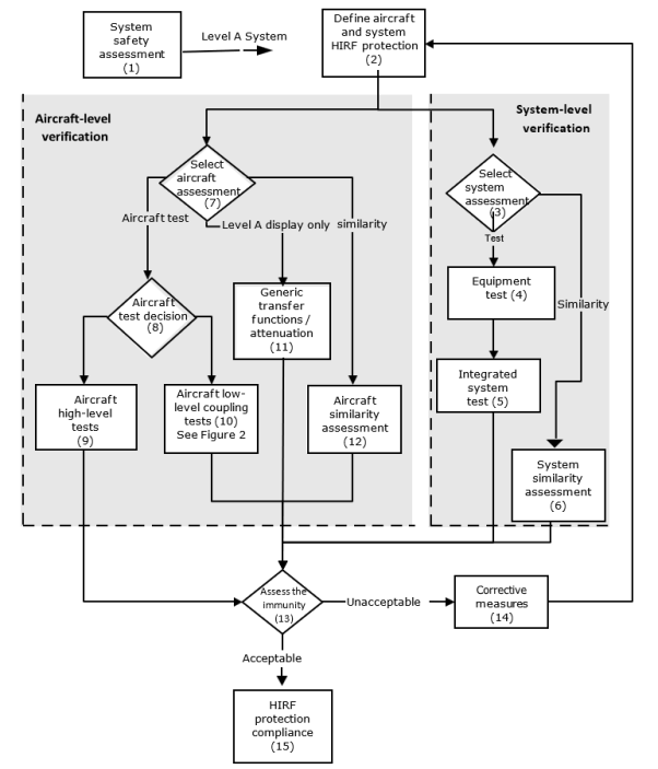
(n) = Step number as described in Section 7 of this AMC
Figure 2: Aircraft low-level coupling tests — Level A systems
![]()
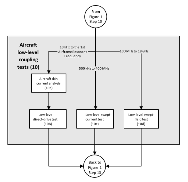
(n) = Step number as described in Section 7 of this AMC
7. STEPS TO DEMONSTRATE ‘LEVEL A’ SYSTEM HIRF COMPLIANCE
Figures 1 and 2 illustrate a process that the applicant can use to demonstrate that their Level A system complies with CS 23.1308(a), 25.1317(a), 27.1317(a), and 29.1317(a).
a. Step 1 — HIRF safety assessment
1. The applicant should determine the system failure condition classification for the systems to be certified on their aircraft, using a system safety assessment as discussed in Section 6(b)(2). For systems classified with catastrophic failure conditions (Level A systems), the applicant should follow compliance steps 2 to 15 listed below, as appropriate. These compliance steps are also depicted in Figures 1 and 2 of this AMC, and are not necessarily accomplished sequentially. Applicants for systems classified with hazardous or major failure conditions (HIRF certification Level B and Level C systems) should follow the compliance steps outlined in Section 8 of this AMC.
2. The system defined for paragraph (a) of CS 23.1308, 25.1317, 27.1317, and 29.1317 is not required to include:
(a) equipment, components and electrical interconnections required only for non-normal situations; or
(b) equipment, components and electrical interconnections required only for dispatching under master minimum equipment lists (MMELs) (when operational suitability data (OSD) is applicable).
3. Some systems include mechanical, hydraulic, and/or pneumatic channels as well as electrical and electronic channel(s) to perform functions whose failure would prevent continued safe flight and landing. The HIRF safety assessment for CS 23.1308(a), 25.1317(a), 27.1317(a), and 29.1317(a) only applies to functions performed by electrical and electronic systems. The HIRF safety assessment should consider electrical or electronic failures that would adversely affect the function of the mechanical, hydraulic, and/or pneumatic channel(s). If electrical or electronic equipment and components, as well as electrical interconnections are used to assist, augment, or monitor for control loop feedback, the mechanical, hydraulic, and/or pneumatic channels in performing the normal operation of the functions with failures that would prevent continued safe flight and landing, then the electrical and electronic channel(s) must comply with CS 23.1308(a), 25.1317(a), 27.1317(a), and 29.1317(a).
4. CS 23.1308(a), 25.1317(a), 27.1317(a), and 29.1317(a) do not require the applicant to assume pre‑existing failure conditions when classifying the functional failure conditions and the scope of Level A systems. The applicant should consider total or partial loss of the systems and malfunctions of the systems, including hazardously misleading information presented to the flight crew during and after the aircraft is exposed to HIRF.
5. CS 23.1308(a)(2), 25.1317(a)(2), 27.1317(a)(2), and 29.1317(a)(2) require that Level A systems automatically recover normal operation of the Level A functions in a timely manner after exposure to HIRF Environment I. Automatic recovery applies to all redundant active channels of the Level A system required for normal operation unless its recovery conflicts with other operational or functional requirements of the system. The exception for automatic recovery conflicts must be based on aircraft operational or functional requirements independent of HIRF exposure. The exception should not be a mitigation for Level A system effects observed after exposure to HIRF Environment I.
6. Appendix 3 Examples of HIRF safety assessment considerations — Level A systems provides examples of systems’ scope based on the guidance above.
b. Step 2 — Define aircraft and system HIRF protection. The applicant should define the HIRF protection features to be incorporated into the aircraft and system designs, based on the HIRF environments that are applicable to their aircraft and its Level A systems. Equipment, system, and aircraft HIRF protection design may occur before aircraft-level tests are performed, and before the actual internal HIRF environment is determined. Therefore, the equipment, system and aircraft HIRF protection design should be based on an estimate of the expected internal HIRF environment. The applicant should consider all aircraft configurations that may affect HIRF protection, such as open landing gear doors (see Step 7).
c. Step 3 — System assessment decision. The applicant should determine whether to perform integrated system HIRF tests on the Level A system, or to base the system verification on previous integrated system HIRF tests performed on a similar system. Aircraft and system tests and assessments need not be performed for HIRF environments above 18 GHz if data and design analysis show the integrated system test results (see Step 5) satisfy the pass/fail criteria from 12 GHz to 18 GHz, and the systems have no circuits that operate in the 18 GHz to 40 GHz frequency range.
d. Step 4 — Equipment test
1. Radiated and conducted RF susceptibility laboratory tests of RTCA / DO-160G / EUROCAE ED-14G (or latest version) Section 20 may be used to build confidence in the equipment’s HIRF immunity before conducting integrated system laboratory tests in Step 5. The equipment should be specified and tested in accordance with the test levels (wire bundle currents injection and RF field illumination) of RTCA / DO-160 / EUROCAE ED-14 Section 20 or to a level estimated for the aircraft and equipment installation using the applicable external HIRF environment.
2. Equipment HIRF tests may be used to augment the integrated system HIRF tests where appropriate. For equipment whose HIRF immunity is evaluated as part of the integrated system-level HIRF tests discussed in Step 5, the individual equipment’s HIRF testing described in this step is optional.
e. Step 5 — Integrated system test
1. Radiated and conducted RF susceptibility laboratory tests on an integrated system should be performed for Level A systems. The HIRF field strengths and wire bundle currents selected for this test should be based on the attenuated external HIRF environment determined in the aircraft assessment (see Steps 10, 11, or 12). In many cases, the integrated system test is performed before the aircraft assessment is complete. In these cases, the integrated system test field strengths and currents should be selected based on the expected aircraft attenuation or transfer function.
2. The installation details for the laboratory integrated system tests should be similar to the installation in the aircraft. For example, the bonding and grounding of the system, wire size, routing, arrangement (whether parallel or twisted wires), connector types, wire shields, and shield terminations, and the relative position of the elements to each other and the ground plane in the laboratory should closely match the system installation on the aircraft to be certified. For this reason, the laboratory integrated system rig should have an Agency conformity inspection prior to conducting any Agency certification credit testing.
3. The integrated system should be tested with the system operating, to include connected displays, sensors, actuators, and other pieces of equipment. Applicants should place the system in various operating modes to ensure the integrated system is tested when operating at its maximum sensitivity. If the connected equipment is not related to the functions with catastrophic failures, these items may be simulated by test sets, if the test sets accurately represent the terminating circuit impedance of the sensor. However, the connected equipment should meet the appropriate HIRF requirements required for its failure condition classification.
4. The test levels should be selected based on the expected aircraft internal HIRF environment determined through aircraft tests (see Step 10), generic transfer functions ‘for Level A display systems only’ and attenuation (see Step 11), or aircraft similarity assessment (see Step 12), using the applicable external HIRF environment. Integrated system test procedures are described in detail in the User’s Guide (SAE ARP 5583A / EUROCAE ED-107A).
5. Wire bundle current injection should be used for frequencies from 10 kHz to 400 MHz. RF currents are injected into the integrated system wiring via a current transformer. Each wire bundle in the system should be injected and the induced wire bundle current measured. If a system wire bundle branches, then each wire bundle branch should also be tested. Simultaneous multi-bundle current injection may be necessary on systems with redundant or multi-channel architectures.
6. High-level radiated susceptibility tests should be used at frequencies greater than 100 MHz. The radiating antenna should be far enough away to ensure the total volume of the equipment and at least half a wavelength of the wiring is simultaneously and uniformly illuminated during the test.
7. The applicant should define appropriate pass/fail criteria for the system, based on the system safety assessment and the appropriate HIRF requirements. Any system susceptibility, including system malfunctions such as displaying hazardously misleading information, upsets, or damage, should be recorded and evaluated based on these previously defined pass/fail criteria.
8. Using only the modulation to which the system under evaluation is most sensitive may minimise the test time. The User’s Guide (SAE ARP 5583A / EUROCAE ED-107A) provides guidance on modulation selection and suggested default modulations and dwell times.
9. The equipment tests in Step 4, using the techniques in RTCA / DO-160G / EUROCAE ED-14G (or latest version) Section 20, normally are not sufficient to show HIRF compliance for Step 5 and Step 6. However, these standard RTCA / DO-160G / EUROCAE ED-14G Section 20 tests may be sufficient if paragraph 7(e)(2) and (3) of this step are met.
10. If the Level A System consists of multiple similar channels, the applicant may propose using one or more channels in the laboratory test set-up for the integrated system, instead of all similar channels. The applicant should demonstrate that the laboratory test set-up adequately performs the functions that must demonstrate compliance with CS 23.1308(a), 25.1317(a), 27.1317(a), and 29.1317(a). The applicant should ensure that the laboratory test set-up represents and monitors any cross-channel interactions, such as cross-channel data links, redundancy management, and system health monitoring.
Note: Similar channels are composed of equipment that has the same hardware but not necessarily the same part number; in case of use of pin programming and/or software to identify or configure equipment of similar channels, it must be assessed whether these differences have an impact on the functions performed.
f. Step 6 — System similarity assessment
1. The integrated system HIRF tests performed for a system previously certified on a given aircraft model may be used to demonstrate system verification for a similar system. Each system considered under the similarity approach needs to be assessed independently even if it may use equipment and installation techniques from previous certification projects.
2. The system used as the basis for similarity must have successfully completed integrated system HIRF tests. A similarity assessment requires a comparison of both the equipment and installation differences that could adversely affect HIRF immunity. The assessment should evaluate the differences between the previously HIRF certified system and the equipment circuit interfaces, wiring, grounding, bonding, connectors, and wire-shielding practices of the equipment that is part of the new system.
3. If the assessment finds only minimal differences between the previously certified system and the new system to be certified, similarity may be used as the basis for system-level verification without the need for additional integrated system tests, provided there are no unresolved in-service HIRF problems related to the previously certified system. If there is uncertainty about the effects of the differences, additional tests and analyses should be conducted, as necessary and appropriate, to resolve the uncertainty. The amount of additional testing should be commensurate with the degree of difference identified between the new system and the system previously certified. If significant differences are found, similarity should not be used as the basis for system-level verification.
g. Step 7 — Aircraft assessment decision
1. Level A systems require an aircraft assessment. The aircraft assessment should determine the actual internal HIRF environment where the Level A systems are installed in the aircraft. The applicant should choose whether to use aircraft tests, previous coupling/attenuation data from similar aircraft types (similarity). For Level A display systems only, applicants should use the generic transfer functions and attenuation in Appendix 1 to this AMC. Alternately, the aircraft assessment may be a test that exposes the entire aircraft with operating Level A systems to external HIRF Environment I, II, or III (Tables 2, 3, and 4 respectively), as appropriate, to demonstrate acceptable Level A system performance.
2. Level A display systems include the display equipment, control panels, and the sensors that provide information to the displays. These sensors could also provide information to Level A non-display systems, so in that case, the applicant should determine the real transfer function and attenuation curves of these sensors when demonstrating compliance for this Level A non-display system. For example, for air data systems and inertial reference systems, which send information to the EFIS and flight controls, the transfer function and attenuation should be determined by aircraft low-level coupling testing or an aircraft similarity assessment as defined in Steps 10 and 12.
3. Other methods for aircraft HIRF assessment, such as analysis, may be acceptable. However, comprehensive modelling and analysis for RF field coupling to the aircraft structure is an emerging technology. Therefore, analysis alone is currently not adequate to show HIRF compliance for Level A systems and should be augmented by testing.
4. If analysis is used to determine aircraft attenuation and transfer function characteristics, test data should be provided to support this analysis. Any analysis results should take into account the quality and accuracy of the analysis. Significant testing, including aircraft-level testing, may be required to support the analysis.
5. Aircraft and system tests and assessments need not be performed for the HIRF environments above 18 GHz if data and design analysis show the integrated system test results (see Step 5) satisfy the pass/fail criteria from 12 to 18 GHz, and the systems have no circuits operating in the 18 to 40 GHz frequency range.
h. Step 8 — Aircraft test decision
1. Various aircraft test procedures are available and accepted for collecting data for aircraft HIRF verification. The two main approaches to aircraft testing are the aircraft high-level test (see Step 9) and the aircraft low-level coupling test (see Step 10). The aircraft high-level field-illumination test involves radiating the aircraft at test levels equal to the applicable external HIRF environment in the HIRF requirements. Aircraft low-level coupling tests involve measuring the airframe attenuation and transfer functions, so that the internal HIRF electric fields and currents can be compared with the integrated system test levels.
2. Some test procedures may be more appropriate than others because of the size of the aircraft and the practicality of illuminating the entire aircraft with the appropriate external HIRF environment. The aircraft low-level coupling tests (see Step 10) may be more suitable for testing large aircraft than the high-level field-illumination test in Step 9, which requires illumination of the entire aircraft with the external HIRF environment.
i. Step 9 — Aircraft high-level tests
1. The aircraft high-level field-illumination test requires generating RF fields external to an aircraft at a level equal to the applicable external HIRF environment.
2. At frequencies below 400 MHz, the distance between the aircraft and the transmitting antenna should be sufficient to ensure the aircraft is illuminated uniformly by the external HIRF environment. The transmitting antenna should be placed in at least four positions around the aircraft. For aircraft, the antenna is typically placed to illuminate the nose, tail, and each wing tip. For rotorcraft, the antenna is typically placed to illuminate the nose, tail, and each side. The aircraft should be illuminated by the antenna at each position while sweeping the frequency range. Perform separate frequency sweeps with the transmitting antenna oriented for horizontal and vertical polarisation. The RF field should be calibrated by measuring the RF field strength in the centre of the test volume before the aircraft is placed there.
3. At frequencies above 400 MHz, the RF illumination should be localised to the system under test, provided all parts of the system and at least one wavelength of any associated wiring (or the total length if less than one wavelength) are illuminated uniformly by the RF field. The applicant may need reflection planes to illuminate relevant apertures on the bottom and top of the aircraft.
4. To ensure the systems are tested when operating at their maximum sensitivity, Level A systems should be fully operational, and the aircraft should be placed in various simulated operating modes.
5. The test time can be minimised by using only the modulation to which the system under evaluation is most sensitive. If the applicant does this, the rationale used to select the most sensitive modulation should be documented in the HIRF test plan as discussed in Section 6(b)(1). The User’s Guide (SAE ARP 5583A / EUROCAE ED-107A) provides guidance on modulation selection and suggested default modulations and dwell times.
6. As an alternative to testing at frequencies below the first airframe resonant frequency, it is possible to inject high-level currents directly into the airframe using aircraft high-level direct-drive test methods. Aircraft skin current analysis should be performed as described in the User’s Guide, or low-level swept‑current measurements should be made to determine the skin current distribution that will exist for different RF field polarisations and aircraft illumination angles so that these can be simulated accurately during this test. Aircraft high-level direct-drive testing, although applicable only from 10 kHz to the first airframe resonant frequency, is advantageous because it is possible to test all systems simultaneously.
j. Step 10 — Aircraft low-level coupling tests
1. General
(a) The aircraft low-level coupling tests include three different tests that cover the frequency range of 10 kHz to 18 GHz (see Figure 2). Detailed descriptions are available in the User’s Guide. Other techniques may be valid, but must be discussed with and accepted by the Agency before being used.
(b) The low-level direct-drive test (see Step 10b, Figure 2) and the low-level swept-current test (see Step 10c) are used for frequencies at or below 400 MHz. The low-level swept-field test (see Step 10d) is used for frequencies at and above 100 MHz. There is an overlap of test frequencies from 100 to 400 MHz in the low-level swept-current test and the low-level swept-field test. The division at 100 MHz is not absolute and depends on the aircraft to be tested and the resonance of the wiring and instrumentation limitations. The division at 400 MHz is not absolute either, and depends on when HIRF penetration of the equipment case becomes a significant factor.
2. Steps 10a and 10b — Aircraft skin current analysis and low-level direct-drive test. Low-level direct‑drive tests in conjunction with skin current analysis should be used to determine the transfer function between the skin current and individual equipment wire bundle currents. The low-level direct‑drive test is typically used for frequencies from 10 kHz to the first airframe resonant frequency. For the low-level direct-drive test to be applied successfully, a three-dimensional model of the aircraft should be derived using aircraft skin current analysis. The three-dimensional model can then be used to derive the aircraft’s skin current pattern for the applicable external HIRF environment. Guidance on skin current analysis is in the User’s Guide. If the relationship between the external HIRF environment and the skin current is known for all illumination angles and polarisation, either because of aircraft skin current analysis or the use of the low-level swept-current test, the skin current can be set up by direct injection into the airframe. The resultant currents on the system wire bundles are measured with a current probe and normalised to 1 V/m electric field strength so they can be scaled to the appropriate external HIRF environment. The low-level direct-drive test is more effective than low-level swept‑current tests for frequencies from 10 kHz to the first airframe resonant frequency, and may be necessary for small aircraft or aircraft with high levels of airframe shielding.
3. Step 10c — Low-level swept-current test. The low-level swept-current test involves illuminating the aircraft with a low-level external HIRF field to measure the transfer function between the external field and the aircraft and equipment wire bundle currents. This test is typically used in the frequency range of 500 kHz to 400 MHz. The transfer function is resonant in nature and is dependent on both the aircraft structure and the system installation. Because the transfer function relates wire bundle currents to the external field, the induced bulk current injection test levels can be related to an external HIRF environment.
The transmitting antenna should be placed in at least four positions around the aircraft, with the distance between the aircraft and the transmitting antenna sufficient to ensure the aircraft is illuminated uniformly. For aircraft, the antenna is typically placed to illuminate the nose, tail, and each wing tip. For rotorcraft, the antenna is typically placed to illuminate the nose, tail, and each side. The aircraft should be illuminated by the antenna at each position while sweeping the frequencies in the range of 500 kHz to 400 MHz. The applicant should perform separate frequency sweeps with the transmitting antenna oriented for horizontal and vertical polarisation, and measure the currents induced on the aircraft wire bundles.
The applicant should calculate the ratio between the induced wire bundle current and the illuminating antenna field strength, and normalise this ratio to 1 V/m. This provides the transfer function in terms of induced current per external field strength unit. Then the current induced by the applicable external HIRF environment can be calculated by multiplying the transfer function by the external HIRF field strength. The calculated HIRF currents for all transmitting antenna positions for each aircraft wire bundle to be assessed should be overlaid to produce worst-case induced current for each wire bundle. These worst-case induced currents can be compared with the current used during the integrated system test in Step 5.
4. Step 10d — Low-level swept-field test. Low-level swept-field testing is typically used from 100 MHz to 18 GHz. The test procedures for the low-level swept-field test are similar to those used for the low-level swept-current test; however, in the low-level swept-field test, the internal RF fields in the vicinity of the equipment are measured instead of the wire bundle currents. Various techniques can be used to ensure the maximum internal field in the vicinity of the equipment is measured. Depending on the size of the aircraft and the size of the aircraft cabin, flight deck, and equipment bays, multipoint measurement or mode stirring can be used to maximise the internal field in the vicinity of the equipment. See the User’s Guide (SAE ARP 5583A / EUROCAE ED-107A) for detailed low-level swept-field test procedures.
k. Step 11 — Generic transfer functions and attenuation — Level A display systems only
1. Level A displays involve functions for which system information is displayed directly to the pilot. For Level A display systems, the aircraft attenuation data may be determined using generic attenuation and transfer function data. This approach should not be used for other Level A systems, such as control systems, because failures and malfunctions of those systems can more directly and abruptly contribute to a catastrophic failure event than display system failures and malfunctions; therefore, other Level A systems should have a more rigorous HIRF compliance verification programme.
2. The integrated system test levels specified in Step 5 may be derived from the generic transfer functions and attenuation for different types of aircraft. Acceptable transfer functions for calculating the test levels are given in Appendix 1 to this AMC. Appendix 1 to this AMC also contains guidelines for selecting the proper generic attenuation. The generic transfer functions show the envelope of the currents that might be expected to be induced in the types of aircraft in an external HIRF environment of 1 V/m. The current levels should be multiplied linearly by HIRF Environment I, II, or III, as appropriate, to determine the integrated system test levels.
3. The internal HIRF electric field levels are the external HIRF environment divided by the appropriate attenuation, in linear units. For example, 20 dB or a 10:1 attenuation means the test level is the applicable external HIRF environment electric field strength reduced by a factor of 10.
4. The internal HIRF environments for Level A display systems can also be measured using on-aircraft low‑level coupling measurements of the actual system installation (see Step 10). This procedure should provide more accurate information to the user, and the test levels may be lower than the generic transfer functions or attenuation, which are worst-case estimates.
l. Step 12 — Aircraft similarity assessment
1. The aircraft attenuation and transfer function tests performed for a previously certified aircraft may be used to support aircraft-level verification for a similar aircraft model. The aircraft used as the basis for similarity must have been previously certified for HIRF compliance, using HIRF attenuation and transfer functions determined by tests on that aircraft.
2. The similarity assessment for the new aircraft model should consider the aircraft differences that could impact on the internal HIRF environment affecting the Level A systems and the associated wiring. The comparison should consider equipment and wiring locations, airframe materials and construction, and apertures that could affect attenuation for the external HIRF environment.
3. If the assessment finds only minimal differences between the previously certified aircraft and the new aircraft to be certified, similarity may be used to determine the aircraft attenuation and transfer functions without the need for additional aircraft tests, providing there are no unresolved in-service HIRF problems related to the existing aircraft. If there is uncertainty about the effects of the differences, additional tests and analyses should be conducted as necessary and appropriate to resolve the uncertainty. The amount of additional testing should be commensurate with the degree of difference identified between the new aircraft to be certified and the aircraft previously certified. If significant differences are found, similarity should not be used as the basis for aircraft-level verification.
m. Step 13 — Assess the immunity
1. The applicant should compare the test levels used for the integrated system test of Step 5 with the internal RF current or RF fields determined by the aircraft low-level coupling tests (see Step 10), the generic transfer functions and attenuation (see Step 11), or the aircraft similarity assessment (see Step 12). The actual aircraft internal RF currents and RF fields should be lower than the integrated system test levels.The comparison method should be included in the HIRF compliance plan. The method should enable a direct comparison between the system test level and the aircraft internal HIRF environment at the equipment or system location, using current for frequencies from 10 kHz to 400 MHz, and using electric field strength for frequencies from 100 MHz through 18 GHz.
2. If the conducted RF susceptibility test levels used for the integrated system test (see Step 5) were too low when compared with the aircraft-induced currents determined in Steps 10b, 10c, 11 or 12, then corrective measures are needed (see Step 14). If the radiated RF susceptibility test levels used for integrated system tests (see Step 5) were too low when compared with the aircraft internal fields determined in Steps 10d, 11 or 12, then corrective measures are needed (see Step 14).
3. When comparing the current measured during low-level swept-current tests in Step 10c with the current used during the integrated system tests in Step 5, there may be differences. These differences may be due to variations between the actual aircraft installation and the integrated system laboratory installation, such as wire bundle lengths, shielding and bonding, and wire bundle composition. The worst-case current signature for a particular wire bundle should be compared with the current induced at the particular test level or equipment malfunction over discrete frequency ranges such as 50 to 500 kHz, 500 kHz to 30 MHz, and 30 to 100 MHz. This comparison should be broken into discrete frequency ranges because the resonant frequencies may differ between the integrated system tests and the aircraft tests.
4. If the applicant uses aircraft high-level tests (see Step 9) for aircraft HIRF verification, they should determine whether there were any Level A system susceptibilities. Any Level A system susceptibilities should be evaluated based on the pass/fail criteria as established in the test plan (see Section 8(b)(1)). If the HIRF susceptibilities are not acceptable, then corrective measures may be needed (see Step 14).
5. HIRF susceptibilities that were not anticipated or defined in the test plan pass/fail criteria may be observed during aircraft high-level tests or integrated system laboratory tests. The pass/fail criteria may be modified if the effects neither cause nor contribute to conditions that adversely affect the aircraft functions or systems in the HIRF requirements. The applicant should provide an assessment and the supporting rationale for any modifications to the pass/fail criteria to the Agency for acceptance.
If the HIRF susceptibilities are not acceptable, then corrective measures may be needed (see Step 14).
6. If the Level A systems show no adverse effects when tested to levels derived from the applicable HIRF Environment I or III, this also demonstrates compliance of the system with HIRF Environment II.
7. If the integrated system test results (see Step 5) satisfy the pass/fail criteria from 12 to 18 GHz, and design analysis shows the system has no circuits operating in the 18 to 40 GHz frequency range, this demonstrates by analysis that the system is not adversely affected when exposed to HIRF environments above 18 GHz. If these conditions are satisfied, further aircraft and system tests and assessments above 18 GHz are not necessary.
8. The applicant should review the actual system installation in the aircraft and the system configuration used for the integrated system test (see Step 5). If significant configuration differences are identified, corrective measures may be needed (see Step 14).
9. Certain RF receivers with antennas connected should not be expected to perform without effects during exposure to the HIRF environments, particularly in the RF receiver operating band. Because the definition of adverse effects and the RF response at particular portions of the spectrum depends on the RF receiver system function, the applicant should refer to the individual RF receiver minimum performance standards for additional guidance. However, because many RF receiver minimum performance standards were prepared before the implementation of the HIRF requirements, the RF receiver pass/fail criteria should be coordinated with the Agency.
10. The applicant should provide the similarity assessment and the supporting rationale to the Agency for acceptance.
n. Step 14 — Corrective measures. Corrective measures should be taken if the system fails to satisfy the HIRF immunity assessment of Step 13. If changes or modifications to the aircraft, equipment, system or system installation are required, then additional tests may be necessary to verify the effectiveness of the changes. The RTCA / DO-160G / EUROCAE ED-14G, or latest version, Section 20 equipment tests, integrated system tests, and aircraft tests, in whole or in part, may need to be repeated to show HIRF compliance.
o. Step 15 — HIRF protection compliance. The test results and compliance report should be submitted to the Agency for approval as part of the overall aircraft type certification or supplemental type certification process.
Figure 3: Routes to HIRF compliance — Level B and Level C systems
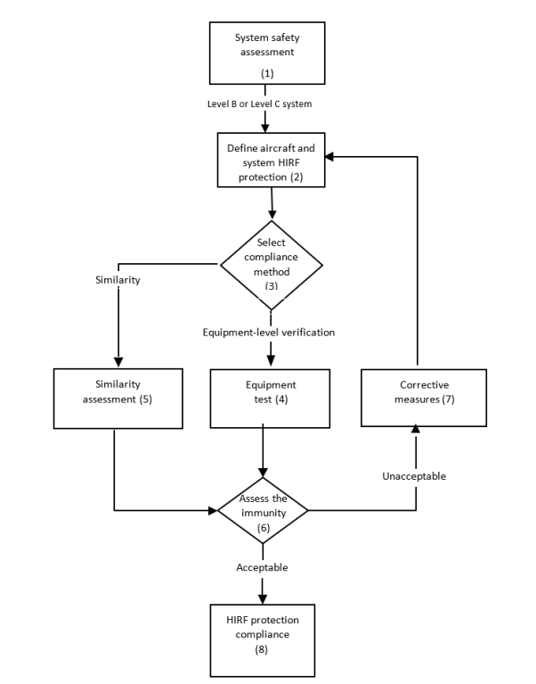
(n) = Step number as described in Section 10 of this AMC
8. STEPS TO DEMONSTRATE ‘LEVEL B’ AND ‘LEVEL C’ SYSTEM HIRF COMPLIANCE
Figure 3 illustrates a process that the applicant can use to demonstrate whether their Level B and Level C systems comply with CS 23.1308(b), 25.1317(b), 27.1317(b), and 29.1317(b), and with CS 23.1308(c), 25.1317(c), 27.1317(c), and 29.1317(c) respectively.
a. Step 1 — HIRF safety assessment. The applicant should determine the system certification level for the systems to be certified on their aircraft, using a system safety assessment as discussed in Section 6(b)(2). For systems classified with hazardous or major failure conditions (Level B and Level C systems), the applicant should follow compliance Steps 2 through 8 listed below, as appropriate. These compliance steps are also depicted in Figure 3 of this AMC and are not necessarily accomplished sequentially. For systems classified with catastrophic failure conditions (Level A systems), the applicant should follow the compliance steps outlined in Section 7.
b. Step 2 — Define the aircraft and system HIRF protection. The applicant should define the HIRF protection features incorporated into the aircraft and system designs, based on the HIRF test levels applicable to their aircraft and its Level B and Level C systems. Equipment, system, and aircraft HIRF protection design may occur before aircraft-level tests are performed, and before the actual internal HIRF environment is determined. Therefore, the equipment, system and aircraft HIRF protection design should be based on an estimate of the expected internal HIRF environment.
c. Step 3 — Select the compliance method. The applicant should determine whether to perform equipment HIRF tests on the Level B and Level C systems, or to base the compliance on previous equipment tests performed for a similar system.
d. Step 4 — Equipment test
1. Level B and Level C systems do not require the same degree of HIRF compliance testing as Level A systems and, therefore, do not require aircraft-level testing. RTCA / DO-160G / EUROCAE ED-14G, or latest version, Section 20 laboratory test procedures should be used, using equipment test levels defined in the applicable specifications. The test levels used depend on whether the system is categorised as Level B or Level C. Equipment HIRF test Level 1 or 2, as applicable, should be used for Level B systems. RTCA / DO‑160 / EUROCAE ED-14 Section 20 Category RR (using the alternative modulation for radiated susceptibility) satisfies the requirements of equipment HIRF test Level 1. For equipment HIRF test Level 2, the applicant may use the approach in Section 9(k) to help determine the acceptable aircraft transfer function and attenuation curves for their Level B system. Equipment HIRF test Level 3 should only be used for Level C systems. RTCA / DO-160 / EUROCAE ED-14 Section 20 Category TT satisfies the requirements of equipment HIRF test Level 3. When applying modulated signals, the test levels are given in terms of the peak of the test signal as measured by a root mean square (rms), indicating the spectrum analyser’s peak detector. See the User’s Guide (SAE ARP 5583A / EUROCAE ED‑107A) for more details on modulation.
2. The applicant should define appropriate pass/fail criteria for the system, based on the system safety assessment and the appropriate HIRF requirements (see Section 6(b)(2)). Any susceptibility noted during the equipment tests, including equipment malfunctions, upsets, or damage, should be recorded and evaluated based on the defined pass/fail criteria.
e. Step 5 — Similarity assessment
1. The equipment HIRF tests performed for a system previously certified on a given aircraft model may be used to show compliance for a similar system. Each system considered for similarity needs to be assessed independently even if it used equipment and installation techniques from a previous certification.
2. The system used as the basis for certification by similarity must have successfully completed equipment HIRF tests and been previously certified for HIRF compliance on another aircraft model. Similarity assessment requires a comparison of both the equipment and installation differences that could adversely affect HIRF immunity. An assessment of a new system should consider the differences in the equipment circuit interfaces, wiring, grounding, bonding, connectors, and wire-shielding practices.
3. If the assessment finds only minimal differences between the previously certified system and the new system to be certified, similarity may be used for HIRF compliance without the need for additional equipment HIRF tests, provided there are no unresolved in-service HIRF problems related to the previously certified system. If there is uncertainty about the effects of the differences, additional tests and analyses should be conducted as necessary and appropriate to resolve the uncertainty. The amount of additional testing should be commensurate with the degree of difference identified between the new system and the system previously certified. If significant differences are found, similarity should not be used as the basis for HIRF compliance.
f. Step 6 — Assess the immunity
1. The applicant should review the results of the equipment test to determine whether the pass/fail criteria are satisfied. HIRF susceptibilities that were not anticipated or defined in the test plan pass/fail criteria may be observed during equipment HIRF tests. The pass/fail criteria may be modified if the effects neither cause nor contribute to conditions that adversely affect the aircraft functions or systems, as applicable, in the HIRF requirements. The applicant should provide an assessment of, and the supporting rationale for, any modifications to the pass/fail criteria to the Agency for approval. If the HIRF susceptibilities are not acceptable, then corrective measures may be needed (see Step 7).
2. The applicant should review the actual system installation in the aircraft and the configuration used for the equipment tests (see Step 4). If significant differences in grounding, shielding, connectors, or wiring are identified, corrective measures may be needed (see Step 7).
3. Certain RF receivers with antennas connected should not be expected to perform without effects during exposure to the HIRF environments, particularly in the RF receiver operating band. Because the definition of adverse effects and the RF response at particular portions of the spectrum depends on the RF receiver system function, applicants should refer to the individual RF receiver minimum performance standards for additional guidance. However, because many RF receiver minimum performance standards were prepared before the implementation of the HIRF requirements, the RF receiver pass/fail criteria should be coordinated with the Agency. Future modifications of the minimum performance standards should reflect the HIRF performance requirements.
g. Step 7 — Corrective measures. The applicant should take corrective measures if the system fails to satisfy the HIRF immunity assessment of Step 6. If changes or modifications to the equipment, system, or system installation are required, then additional tests may be necessary to verify the effectiveness of the changes. The RTCA / DO-160G / EUROCAE ED-14G, or latest version, Section 20 equipment tests, in whole or in part, may need to be repeated to show HIRF compliance.
h. Step 8 — HIRF protection compliance. The applicant should submit the test results and compliance report to the Agency for acceptance as part of the overall aircraft type certification or supplemental type certification process.
9. HIRF COMPLIANCE DEMONSTRATION
a. HIRF compliance plan. An overall HIRF compliance plan should be established to clearly identify and define HIRF certification requirements, HIRF protection development, and the design, test, and analysis activities intended to be part of the compliance effort. This plan should provide definitions of the aircraft systems, installations, and protective features against which HIRF compliance will be assessed. The HIRF compliance plan should be discussed with, and submitted to, the Agency for acceptance before initiating HIRF compliance activities. If the aircraft, system, or installation design changes after approval, a revised HIRF compliance plan should be submitted to the Agency for acceptance. The HIRF compliance plan should include the following:
1. a HIRF compliance plan summary;
2. identification of the aircraft systems, with classifications based on the safety assessment as it relates to HIRF (see Section 6(b)(2));
3. the planned or expected HIRF environment for the aircraft and installed systems; and
4. the verification methods, such as test, analysis, or similarity.
b. Methods of compliance verification
1. Various methods are available to aid in demonstrating HIRF compliance. Methods acceptable to the Agency are described in Sections 6 and 7 of this AMC. Figures 1 and 2 above outline the steps to HIRF compliance for systems that require Level A HIRF certification. Figure 3 above outlines the steps to HIRF compliance for systems that require Level B or Level C HIRF certification. The steps in these figures are not necessarily accomplished sequentially. Wherever a decision point is indicated on these figures, the applicant should complete the steps in that path as described in Sections 6 and 7 of this AMC.
2. Other HIRF compliance techniques may be used to demonstrate system performance in the HIRF environment; however, those techniques should be accepted by the Agency before using them.
c. HIRF verification test, analysis, or similarity plan. Test, analysis and similarity are all acceptable methods. The applicant must choose the method or the combination of methods most appropriate for their project. See Sections 6 and 7 of this AMC, and SAE ARP 5583A / EUROCAE ED-107A for additional guidance for selecting the appropriate method. Specific HIRF test, analysis, or similarity plans could be prepared to describe specific verification activities. A single verification plan combining various methods for all the selected systems or dedicated verification plans may be necessary. For example, there may be several systems or equipment laboratory test plans, an aircraft test plan, or a similarity plan for selected systems on an aircraft.
1. Test plan
(a) A HIRF compliance test plan may include the equipment, system, and aircraft test objectives for the acquisition of data to support HIRF compliance verification. The plan should provide an overview of the factors to be addressed for each system test requirement.
The test plan should include:
1. the purpose of the test;
2. a description of the aircraft and/or the system to be tested;
3. system configuration drawings;
4. the proposed test set-up and methods;
5. the intended test levels, modulations, and frequency bands;
6. pass/fail criteria; and
7. the test schedule and test location.
(b) The test plan should cover Level A, B, and C systems and equipment, as appropriate. Level A systems may require both integrated systems laboratory tests and aircraft tests. Level B and Level C systems and equipment require only equipment laboratory testing.
(c) The test plan should describe the appropriate aspects of the systems to be tested and their installation. Additionally, the test plan should reflect the results of any analysis performed in the overall process of the HIRF compliance evaluation.
2. Analysis plan. A HIRF compliance analysis plan should include the objectives, both at system and equipment level, for generating data to support HIRF compliance verification. Comprehensive modelling and analysis for RF field coupling to aircraft systems and structures is an emerging technology; therefore, the analysis plan should be coordinated with the Agency to determine an acceptable scope for the analysis.
The analysis plan should include:
(a) the purpose and scope of the analysis;
(b) a description of the aircraft and/or the system addressed by the analysis;
(c) system configuration descriptions;
(d) the proposed analysis methods;
(e) the approach for validating the analysis results; and
(f) pass/fail criteria, including margins to account for analysis uncertainty.
3. Similarity plan. A similarity plan should describe the approach undertaken to use the certification data from previously certified systems, equipment, and aircraft in the proposed HIRF compliance programme.
The similarity plan should include:
(a) the purpose and scope of the similarity assessment;
(b) the specific systems addressed by the similarity assessment;
(c) the data used from the previously certified systems, equipment, and aircraft;
(d) details of the significant differences between the aircraft and system to be certified and the similar aircraft and system from which the data will be used; and
(e) when data has limited substantiation, a description and justification for margins to account for similarity uncertainty; see Section 6(f)(3) for additional information on margins.
d. Compliance reports. One or more compliance reports may be necessary to document the results of test, analysis, or similarity assessments. For new or significantly modified aircraft, HIRF compliance reports include many system and equipment test reports, aircraft test reports, and HIRF vulnerability analysis reports. For these types of HIRF certification programmes, a compliance summary report may be useful to summarise the results of tests and analyses. For HIRF certification programmes of relatively simple systems, a single compliance report is adequate.
1. Test reports. Comprehensive test reports should be produced at the conclusion of HIRF compliance testing. The test reports should include descriptions of the salient aspects of equipment or system performance during the test, details of any area of non-compliance with HIRF requirements, actions taken to correct the non-compliance, and any similarity declarations. The applicant should also provide the supporting rationale for any deviations from system performance observed during testing.
2. Analysis reports. Analysis reports should describe the details of the analytical model, the methods used to perform the analysis, and the results of the analysis. The reports should identify any modelling uncertainty and justify the margins established in the analysis plan.
3. Similarity reports. Similarity reports should document the significant aircraft, system, equipment, and installation features that are common between the aircraft or system that is the subject of the similarity analysis and the aircraft or system that was previously certified for HIRF. The reports should identify all the significant differences encountered, along with the assessment of the impact of these differences on HIRF compliance. These reports should also justify the margins established in the similarity plan.
10. MAINTENANCE, PROTECTION ASSURANCE, AND MODIFICATIONS
a. The minimum maintenance required to support HIRF certification should be identified in the instructions for continued airworthiness (ICAs) as specified in CS 23.1529, 25.1529, 25.1729, 27.1529, and 29.1529, as appropriate. Dedicated devices or specific features may be required to provide HIRF protection for an equipment or system installation. Appropriate maintenance procedures should be defined for these devices and features to ensure in-service protection integrity. A HIRF protection assurance programme should be proposed in the certification plan to identify all actions necessary to justify or to verify that the maintenance procedures are adequate. This assurance programme may propose a surveillance programme based on a sampling of the fleet for monitoring the effectiveness of the protection features and/or maintenance procedures. The User’s Guide (SAE ARP 5583A / EUROCAE ED107A) provides further information on these topics.
b. The maintenance procedures should consider the effects of corrosion, fretting, flexing cycles, or other causes that could degrade these HIRF protection devices. Whenever applicable, specific replacement times of these devices and features should be identified.
c. Aircraft or system modifications should be assessed for the impact that any changes will have on the HIRF protection. This assessment should be based on analysis and/or measurement.
[Amdt 20/23]
Appendix 1 to AMC 20-158A — Definitions and acronyms
ED Decision 2022/001/R
1. Definitions
Adverse effect: a response of a system that results in an unexpected and unacceptable operation of an aircraft system, or unexpected and unacceptable operation of the function performed by the system.
Attenuation: the term used to denote a decrease in the electromagnetic field strength in the transmission from one point to another. Attenuation may be expressed as a scalar ratio of the input magnitude to the output magnitude, or in decibels (dB).
Automatically recover: a return to normal operations without pilot action.
Bulk current injection: a method of electromagnetic interference (EMI) testing that involves injecting current into wire bundles through a current injection probe.
Channel: a subset of a system consisting of equipment, components, and interconnections, which performs an aircraft function provided by the system. A system could be composed of redundant similar or dissimilar channels in order to maintain the function at the aircraft level in case of failure on one or several channels.
Continued safe flight and landing: the capability for continued controlled flight and landing at a suitable location, possibly using emergency procedures, but without requiring exceptional piloting skill or strength. For CS-25 aeroplanes, the pilot must be able to land safely at a suitable airport. For CS-23 aeroplanes, it is not necessary to land at an airport. For rotorcraft, the rotorcraft must continue to cope with adverse operating conditions, and the pilot must be able to land safely at a suitable site. Some aircraft damage may be associated with a failure condition during flight or upon landing.
Continuous wave: an RF signal consisting of only the fundamental frequency with no modulation in amplitude, frequency, or phase.
Coupling: the process whereby electromagnetic energy is induced in a system by radiation produced by an RF source.
Current injection probe: an inductive device designed to inject RF signals directly into wire bundles when clamped around them.
Direct drive test: an electromagnetic interference (EMI) test that involves electrically connecting a signal source directly to the unit to be tested.
Electrical and electronic system: an electrical or electronic system includes all the electrical and electronic equipment, components, elements and the electrical interconnections that are required to perform a particular function.
Equipment: a component of an electrical or electronic system with interconnecting electrical conductors.
Equipment electrical interface: a location on a piece of equipment where an electrical connection is made to the other equipment in a system of which it is a part. The electrical interface may consist of individual wires or wire bundles that connect the equipment.
External HIRF environment: electromagnetic RF fields at the exterior of an aircraft.
Field strength: the magnitude of the electromagnetic energy propagating in free space expressed in volts per metre (V/m).
Function: the specific action of a system, equipment, and flight crew performance aboard the aircraft that, by itself, provides a completely recognisable operational capability. For example, ‘display aircraft heading to the pilots’ is a function. One or more systems may perform a specific function, or one system may perform multiple functions.
HIRF environment: the electromagnetic environment created by the transmission of high-power RF energy into free space.
HIRF vulnerability: the susceptibility characteristics of a system that cause it to suffer adverse effects when performing its intended function as a result of having been subjected to a HIRF environment.
Immunity: the capacity of a system or piece of equipment to continue to perform its intended function, in an acceptable manner, in the presence of RF fields.
Interface circuit: an electrical or electronic device connecting the electrical inputs and outputs of a piece of equipment to other pieces of equipment or devices in an aircraft.
Internal HIRF environment: the RF environment inside an airframe, equipment enclosure, or cavity. The internal RF environment is described in terms of the internal RF field strength or wire bundle current.
Margin: the difference between the equipment susceptibility or qualification levels and the aircraft internal HIRF environment. Margin requirements may be specified to account for uncertainties in design, analysis, or test.
Modulation: the process whereby certain characteristics of a wave, often called the carrier wave, are varied in accordance with an applied function.
Non-normal situation: any situation that requires non-normal, abnormal, emergency, unusual procedures, or configurations for operating an aircraft.
Normal operation: a status where the system performs its intended function. When addressing compliance with CS 23.1308(a)(2), 25.1317(a)(2), 27.1317(a)(2), and 29.1317(a)(2), the function whose failure would prevent the continued safe flight and landing should be in the same undisturbed state as before exposure to the HIRF threat, while other functions, performed by the same system, subject to CS 23.1308(b) and (c), 25.1317(b) and (c), 27.1317(b) and (c), and 29.1317(b) and (c), are not required to be recovered. The system that performs the function may be nevertheless in a different state as long as the function is not adversely affected.
Radio frequency (RF): a frequency useful for radio transmission. The present practical limits of RF transmissions are roughly 10 kilohertz (kHz) to 100 gigahertz (GHz). Within this frequency range, electromagnetic energy may be detected and amplified as an electric current at the wave frequency.
Reflection plane: a conducting plate that reflects RF signals.
Similarity: the process of using existing HIRF compliance documentation and data from a system or an aircraft to demonstrate HIRF compliance for a nearly identical system or aircraft of equivalent design, construction, and installation.
Susceptibility: a property of a piece of equipment that describes its inability to function acceptably when subjected to unwanted electromagnetic energy.
Susceptibility level: the level where the effects of interference from electromagnetic energy become apparent.
Transfer function: the ratio of the electrical output of a system to the electrical input of a system, expressed in the frequency domain. For HIRF, a typical transfer function is the ratio of the current on a wire bundle to the external HIRF field strength, as a function of frequency.
Timely manner: timely recovery has been introduced to account for the necessary period for complex systems to reconfigure safely after a disruption. The meaning of ‘in a timely manner’ therefore depends upon the function performed by the system to be evaluated, the specific system design, the interactions between that system and other systems, and interactions between the system and the flight crew. The definition of ‘in a timely manner’ must be determined for each specific system and for the specific functions performed by the system. The applicable definition could be included in the HIRF compliance plan for review and concurred with the Agency.
Upset: an impairment, either permanent or momentary, of the system operation. For example, a change of digital or analogue state that may or may not require a manual reset.
User’s Guide: this refers to SAE Document ARP 5583A or EUROCAE Document ED-107A.
2. Acronyms
|
AC: |
advisory circular |
|
AMC: |
acceptable means of compliance |
|
ARP: |
aerospace recommended practice |
|
CS: |
certification specification |
|
DAL: |
development assurance level (ED-79A / ARP 4754A) / design assurance level (ED‑80 / DO-254) |
|
EASA: |
European Union Aviation Safety Agency |
|
EWIS: |
electrical wiring interconnection systems |
|
EUROCAE: |
European Organisation for Civil Aviation Equipment |
|
FDAL: |
functional development assurance level (ED-79A / ARP 4754A) |
|
HCL: |
HIRF certification level |
|
HIRF: |
high-intensity radiated field |
|
ICAs: |
instructions for continued airworthiness |
|
IDAL: |
item development assurance level (ED-79A / ARP 4754A) |
|
RTCA: |
Radio Technical Commission for Aeronautics |
|
SAE: |
Society of Automotive Engineers |
[Amdt 20/23]
Appendix 2 to AMC 20-158A — Generic transfer functions and attenuation
ED Decision 2022/001/R
1. Generic transfer functions
a. Suitable transfer functions for calculating the bulk current injection test levels for Level A display systems (see Section 8(k)) are given in Figures A1-1 through A1-5. These are derived generic transfer functions acquired from test results obtained from a significant number of aircraft. The test results were processed to establish a 95 per cent population probability.
b. The transfer functions are normalised to a 1 V/m HIRF environment and may be multiplied linearly by the external HIRF environment to establish the bulk current injection test level requirements in the frequency range from 10 kHz up to 400 MHz. For example, if the HIRF environment is 100 V/m at 3 MHz, then using Figure A1-1, multiply 0.7 mA/V/m by 100 V/m to establish a test level of 70 milliamperes (mA).
c. Consult the User’s Guide (SAE ARP 5583A / EUROCAE ED-107A) for details on the use of generic transfer functions.
Figure A1-1: Generic transfer function — Aeroplanes
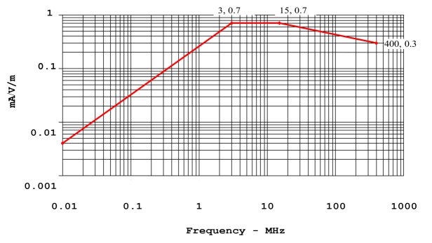
Note: Generic transfer function normalised to 1 V/m for an aircraft with a fuselage length of ≤ 25 m.
Figure A1-2: Generic transfer function — Aeroplanes
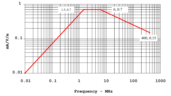
Note: Generic transfer function normalised to 1 V/m for an aircraft with a fuselage length of > 25 m and ≤ 50 m.
Figure A1-3: Generic transfer function — Aeroplanes
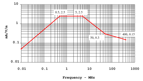
Note: Generic transfer function normalised to 1 V/m for an aircraft with a fuselage length of > 50 m.
Figure A1-4: Generic transfer function — Rotorcraft
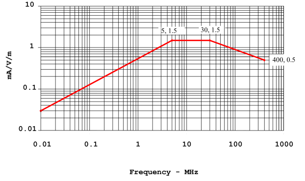
Note: Generic transfer function normalised to 1 V/m for a rotorcraft.
Figure A1-5: Generic transfer function — All aircraft
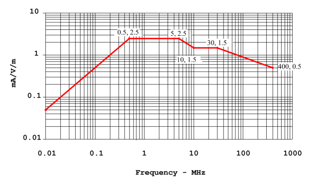
Note: Generic transfer function normalised to 1 V/m for all aircraft.
2. Generic attenuation
a. Figure A1-6 shows the generic attenuation for frequencies from 100 MHz to 18 GHz that can be used for determining the internal HIRF environment where the equipment and associated wiring for Level A display systems (see Section 9(k)) are installed. This internal HIRF environment provides the test level for the integrated system radiated susceptibility laboratory test. The external HIRF environment should be divided by the appropriate attenuation, in linear units, to determine the internal HIRF environment. For example, 12 dB or a 4:1 attenuation means that the test level is the applicable external HIRF environment electric field strength reduced by a factor of 4.
b. Guidance on the use of the generic attenuation is given below:
1. No attenuation. No attenuation credit can be used when the Level A display equipment and the associated wiring are located in aircraft areas with no HIRF shielding, such as areas with unprotected, non-conductive composite structures, areas where there is no guarantee of structural bonding, or other open areas where no shielding is provided. The applicant may choose to use no attenuation for equipment that may be installed in a broad range of aircraft areas.
2. 6 dB attenuation. This attenuation is appropriate when the Level A display equipment and the associated wiring are located in aircraft areas with minimal HIRF shielding, such as a cockpit in a non-conductive composite fuselage with minimal additional shielding, or areas on the wing leading or trailing edges, or in wheel wells.
3. 12 dB attenuation. This attenuation is appropriate when the Level A display equipment and the associated wiring are located entirely within aircraft areas with some HIRF shielding, in aircraft with a metal fuselage or a composite fuselage with shielding effectiveness equivalent to metal. Examples of such areas are avionics bays not enclosed by bulkheads, cockpits, and areas near windows, access panels, and doors without EMI gaskets. Current-carrying conductors in this area, such as hydraulic tubing, control cables, wire bundles, and metal wire trays, are not all electrically bonded to the bulkheads they pass through.
4. 20 dB attenuation. This attenuation is appropriate when the Level A display equipment and the associated wiring are located entirely within aircraft areas with moderate HIRF shielding, in aircraft with a metal fuselage or a composite fuselage with shielding effectiveness equivalent to metal. In addition, wire bundles passing through bulkheads in these areas have shields electrically bonded to the bulkheads. Wire bundles are installed close to metal structure and take advantage of other inherent shielding characteristics provided by metal structure. Current-carrying conductors, such as hydraulic tubing, cables, and metal wire trays are electrically bonded to all the bulkheads they pass through.
5. 32 dB attenuation. This attenuation is appropriate when the level A display equipment and all the associated wiring to and from equipment are located entirely within areas with very effective HIRF shielding to form an electromagnetic enclosure.
6. Generic attenuation for rotorcraft. Display units installed in rotorcraft typically have minimal attenuation unless specific shielding is provided in the bulkhead, glare shield, panel, and doors.
c. Different attenuation values may be appropriate for different frequency ranges. For example, 0 dB attenuation may be used for the frequency range of 100 to 400 MHz, 6 dB attenuation for the frequency range of 400 MHz to 1 GHz, and 12 dB attenuation for the frequency range of 1 to 18 GHz. If an applicant intends to use different attenuation values for various frequency ranges, then they should also provide the supporting rationale.
d. Consult the User’s Guide (SAE ARP 5583A / EUROCAE ED-107A) for details on the use of generic attenuation.
3. Measured transfer functions or attenuation
The applicant may produce their own generic transfer functions and attenuation for their Level A display systems (see Section 9(k)) based on actual measurements on their aircraft models. These transfer functions and the attenuation can then be used in their HIRF compliance submission in place of the generic transfer functions and attenuation specified in this Appendix. The Agency encourages this approach because it provides a more accurate reflection of the true internal HIRF environment for aircraft models. However, if an applicant intends to produce their own generic transfer functions and attenuation, then this approach should also be addressed in the HIRF compliance plan (see Section 6(a)) that is submitted to the Agency for acceptance.
Figure A1-6: Generic attenuation values — All aircraft
100 MHz to 18 GHz
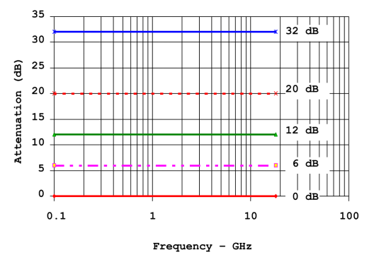
[Amdt 20/23]
Appendix 3 to AMC 20-158A — Examples of HIRF safety assessment considerations — Level A systems on large aeroplanes
ED Decision 2022/001/R
1. Establishing appropriate pass/fail criteria for complying with CS 25.1317(a) can only be achieved through a comprehensive review of the system design using an acceptable HIRF functional hazard assessment process in the form of a system HIRF certification level (HCL). The following paragraphs summarise the approaches whereby pass/fail criteria for compliance with CS 25.1317(a) are specified on the merit of specific system architecture attributes.
2. For the purposes of discussion and evaluation of the examples, the architectural strategies used in the system implementation need to be defined. Therefore, the additional definitions below should be considered:
a. Similar redundant channels: the multiple channels consist of equipment, components, electrical interconnections and configurations that are similar, typically with pieces of equipment that have identical part numbers. The channels should be independent. They may be configured in active, active-backup and passive-backup modes.
b. Dissimilar redundant channels: each channel is unique and independent of the others. They may be configured in active, active-backup and passive-backup modes.
c. Combination of similar and dissimilar redundant channels: the combination of similar and dissimilar channels, as defined above, with independence between channels. They may be configured in active, active-backup and passive-backup modes.
Notes:
a. ‘Active mode’ means that the channel performs the aircraft function in normal operation.
b. ‘Active-backup mode’ means that the channel is operational but not used to perform the aircraft function until switched to active mode either automatically or by flight crew action.
c. ‘Passive-backup mode’ means that the channel is not operational; switching to active mode is either automatic or by flight crew action upon failure recognition.
d. ‘Combination of electrical/electronic and mechanical, hydraulic and/or pneumatic channels’: certain architectures combine electrical and electronic channels with mechanical, hydraulic and/or pneumatic channels. These combinations of electrical/electronic and mechanical, hydraulic or pneumatic channels may be configured in active, active-backup and passive-backup modes.
e. These examples are theoretical and intended to facilitate the discussion from which universal guidelines may be derived to help develop useful guidance material. It is not the intention to account for all possible configurations but only to represent the common system architectures or some that present unique challenges.
3. This Appendix presents examples of large aeroplane systems with multiple independent and redundant channels that perform a function whose failure would prevent continued safe flight and landing.
These examples could also be used for other types of aircraft.
|
Example 1 |
|||
|
Function |
25.1317(a) |
||
|
Channel |
Channel |
Channel |
|
|
Display of attitude, altitude, and airspeed information to the pilots during IFR operations (e.g. primary display system and associated sensors, with dissimilar standby display system and sensors) |
Active
(Pilot displays and associated sensors) |
Active
(Co-pilot displays and associated sensors) |
Active-backup
(Dissimilar standby display and associated sensors) |
|
Requirements for compliance demonstration (CS 25.1317) |
(a)(1), (a)(2), (a)(3) |
(a)(1), (a)(2), (a)(3) |
(b) |
|
Discussion:
This example depicts the specification of CS 25.1333 for independent displays of information essential to the safety of flight at each pilot station. The standby display is required in order to achieve the safety objectives of CS 25.1309. Either the pilot or the co-pilot can be the pilot flying (PF) or pilot monitoring (PM) during normal operations, so both the pilot and the co-pilot display systems should be considered as active systems.
Compliance with CS 25.1317(a)(1), (a)(2), and (a)(3) should demonstrate that neither pilot display of aircraft attitude, altitude, and airspeed is adversely affected and recovers normal operation of these Level A functions when the aircraft is exposed to HIRF Environment I and II. It is acceptable that the dissimilar standby display demonstrates compliance with the CS 25.1316(b) requirements. The adverse effects must include both a loss of, and hazardously misleading, attitude, altitude, and airspeed information. |
|||
|
Example 2 |
|||
|
Function |
25.1317(a) System |
||
|
Channel |
Channel |
Channel |
|
|
Full authority control of pitch, yaw, and roll using electrical and electronic flight control systems |
Active or active‑backup
(Flight control system #1) |
Active or active‑backup
(Flight control system #2) |
Active or active‑backup
(Flight control system #3) |
|
Requirements for compliance demonstration (CS 25.1317) |
(a)(1), (a)(2), (a)(3) |
(a)(1), (a)(2), (a)(3) |
(a)(1), (a)(2), (a)(3) |
|
Discussion: This example depicts an electronic flight control system that comprises three independent channels to meet the safety objectives of CS 25.1309. At any time, any one of the three channels can operate as the active channel. Only one channel operates in an active mode while the others are in active-backup mode. Any channel can perform the control function at any time; therefore, all the channels must comply with CS 25.1317(a)(1), (a)(2), and (a)(3). |
|||
|
Example 3 |
|||
|
Function |
25.1317(a) System |
||
|
Channel |
Channel |
Channel |
|
|
Provide engine overspeed protection
|
Active (Electronic engine control system)
(Normal speed control) |
Active or active‑backup (Electronic engine control system)
(Overspeed protection) |
Active
(Independent mechanical overspeed protection) |
|
Requirements for compliance demonstration (CS 25.1317) |
(b) |
(b) |
Not subject to CS 25.1317 |
|
Discussion: This example depicts the function of engine overspeed protection performed by a combination of active electrical and electronic control and mechanical system control. The mechanical channel must provide overspeed protection during normal operations, and be independent of the active electronic control channels. The mechanical channel must not rely on electrical or electronic components to assist, augment, or monitor the overspeed protection. If the mechanical channel is independent of the electronic engine control speed control and overspeed protection, and has no electrical or electronic components that have failure modes that could prevent overspeed protection, then the engine overspeed protection function is not adversely affected when the aircraft is exposed to HIRF Environment I and II. The system is, therefore, not subject to CS 25.1317(a). The electronic engine control channels should comply with CS 25.1317(b). This example only considers the overspeed protection feature implemented by the system. Other functions whose failure may be classified as catastrophic, such as the loss of thrust control function where the function may be implemented by electronic control channels, should comply with CS 25.1317(a). |
|||
|
Example 4 |
|||
|
Function |
25.1317(a) System |
||
|
Channel |
Channel |
Channel |
|
|
Provide electrical power for electrical and electronic systems including those with catastrophic failure conditions
|
Active
(Left engine generator system) |
Active
(Right engine generator system) |
Passive-backup
(Emergency power supply system driven by ram-air turbine) |
|
Requirements for compliance demonstration (CS 25.1317) |
(a)(1), (a)(2), (a)(3) |
(a)(1), (a)(2), (a)(3) |
(b) |
|
Discussion: This example depicts a typical transport category aircraft electrical system on a twin-engined aircraft where two or more independent sources of electrical power are required by CS 25.1307(b) and a ram-air turbine is necessary to meet the safety objectives of CS 25.1309 and CS 25.1351(d). For this example, the electrical system consists of two active channels provided by a single main-engine-driven generator on each engine with the associated distribution and controls, and a third passive-backup channel provided by a ram-air turbine electrical power system. The ram-air turbine electrical power system is stowed during normal operation and deployed either automatically and/or manually when power from the two main-engine-driven generators is lost. The active engine generator system channels must not be adversely affected when the aircraft is exposed to HIRF Environment I and II, and comply with CS 25.1317(a)(1), (a)(2), and (a)(3). The passive‑backup ram-air turbine electrical power system does not mitigate adverse effects for compliance with CS 25.1317(a). It is acceptable that the ram-air turbine electrical power system demonstrates compliance with the CS 25.1317(b) requirements. |
|||
|
Example 5 |
||||
|
Function |
25.1317(a) System |
|||
|
Channel |
Channel |
Channel |
Channel |
|
|
Provide electrical power for electrical and electronic systems including those with catastrophic failure conditions
|
Active
(Left engine generator system) |
Active
(Right engine generator system) |
Active
(APU-driven generator system required for ETOPS flight beyond 180')
|
Passive-backup
(Emergency power supply driven by |
|
Requirements for compliance demonstration (CS 25.1317) |
(a)(1), (a)(2), (a)(3) |
(a)(1), (a)(2), (a)(3) |
(a)(1), (a)(2), (a)(3) |
(b) |
|
Discussion: This example depicts a twin-engined transport category aircraft electrical system where two or more independent sources of electrical power are required by CS 25.1307(b) and an alternate source (driven by a ram-air turbine) is necessary to meet the safety objectives of CS 25.1309 and CS 25.1351(d). This configuration includes a third electrical power source driven by an auxiliary power unit (APU). This third source is required (active channel) for ETOPS beyond 180 minutes. As in Example 4, the emergency power source is a passive-backup channel provided by a ram-air turbine that remains stowed during normal flight and deployed either automatically and/or manually when power from all other channels is lost. All active electrical power generation channels should comply with CS 25.1317(a)(1), (a)(2), and (a)(3). The passive-backup electrical power generation channel does not mitigate the adverse effects due to HIRF exposure to meet the intent of the HIRF requirements. It is acceptable that the passive-backup channel demonstrate compliance with CS 25.1316(b) requirements. Note: For non-ETOPS or for ETOPS up to 180' aircraft, the APU HIRF certification level should be defined based on the specific aircraft safety assessment. |
||||
|
Example 6 |
||||
|
Function |
25.1317(a) System |
25.1317 System |
25.1317 System |
System |
|
Channel |
Channel |
Channel |
Channel |
|
|
Reduce aircraft speed on ground in a controlled manner using thrust reverser control system, spoiler deployment system, and wheel braking system |
Active
Main brake system (Electro-mechanical) |
Active
(Electronic engine thrust reverse control with associated sensors) |
Active
(Electronic spoiler deployment control with associated sensors) |
Active
(Independent mechanical wheel braking) |
|
Requirements for compliance demonstration |
(a)(1), (a)(2), (a)(3)
|
25.1317(a), (b) or (c) depending on specific aircraft safety assessment |
25.1317(a), (b) or (c) depending on specific aircraft safety assessment |
Not subject to |
|
Discussion: This example depicts an aircraft-level function that is performed by a combination of independent systems each contributing in part to the function during a specific phase of flight. In this case, each system implements a very distinct aircraft-level function that serves in a complementary manner to decelerate the aircraft during the landing roll. The mechanical wheel braking system is assumed to be independent of the other channels, with no associated electrical or electronic equipment to assist, augment, or monitor the mechanical wheel braking system. In this example, it is assumed that the main brake system includes failure conditions that are catastrophic. For the electronic engine thrust reverser control and the electronic spoiler control systems, the applicable parts of CS 25.1317 would depend on the specific failure conditions. The effectiveness, authority, and malfunctions associated with each system should be considered. Additionally, the interaction between the systems has also to be considered. Issues such as asymmetrical thrust reverser activation or spoiler deployment could adversely affect the main brake and mechanical wheel braking functions and could affect the safety classification for the thrust reverser and spoiler controls. An aircraft safety assessment must be carried out for each of these systems that perform a specific aircraft-level function to identify and classify their failure conditions. The failure hazard classifications and the decomposition of each system into the constituent channels would then dictate which paragraphs of CS 25.1317 are needed. |
||||
|
Example 7 |
|||
|
Function |
25.1317(a) System
|
||
|
Channel |
Channel |
Channel |
|
|
Provide altitude information to be displayed in IFR flight using air-data computer connected to the primary flight display (PFD), and pneumatic standby instrument with alternate static port |
Active
(Air-data computer 1 with static port) |
Active
(Air-data computer 2 with static port) |
Active-backup
(Pneumatic standby altimeter with alternate static port) |
|
Requirements for compliance demonstration (CS 25.1317) |
(a)(1), (a)(2), (a)(3) |
(a)(1), (a)(2), (a)(3) |
Not subject to |
|
|
|
|
|
|
Discussion: This example depicts the function to provide altitude information. The main sources are two air-data computers (ADCs) coupled to static ports and a backup source from a standby pneumatic altimeter coupled to an alternate static port independent from the main static ports. In such a case, the standby altimeter does not mitigate compliance with CS 25.1317(a) for the active ADC channels. The standby altimeter does not mitigate the common hazardously misleading altitude information from the active ADC channels for compliance with CS 25.1317(a). |
|||
|
Function |
25.1317(a) System |
||
|
Channel |
Channel |
Channel |
|
|
Control and protection of the aircraft pneumatic (bleed) system
(Top-level failure condition classification: catastrophic) |
Active
(Pneumatic system controller #1)
FDAL B / IDAL B
|
Active
(Pneumatic system controller #2)
FDAL B / IDAL B |
Passive-backup
(High pressure switch + valve)
FDAL C / IDAL C |
|
Requirements for compliance demonstration (CS 25.1317) |
(a)(1), (a)(2), (a)(3)
|
(a)(1), (a)(2), (a)(3) |
(b) |
|
Discussion: This is a generic example with the objective to show that not rarely the HIRF certification level (HCL) of a given system will be different from the functional development assurance level (FDAL) and item development assurance level (IDAL), defined according to SAE ARP 4754A / EUROCAE ED‑79A Guidelines for Development of Civil Aircraft and Systems. Therefore, it is important to use the proper nomenclature and avoid SAE ARP 4754A / EUROCAE ED‑79A ‘DAL’ or similar terms when referring to the HCL. In this example, the pneumatic control system is composed of two main active controllers and a simpler passive-backup channel that can perform the function, preventing the catastrophic event in case of the failure of both controllers. The FDAL for each channel or member (SAE ARP 4754A / EUROCAE ED-79A nomenclature) was defined for a catastrophic top-level failure condition based on the ‘Option 2’ column 4 of Table 3 DEVELOPMENT ASSURANCE LEVEL ASSIGNMENT TO MEMBERS OF A FUNCTIONAL FAILURE SET of SAE ARP 4754A / EUROCAE ED-79A, which allows the combination of FDALs B+B+C for independent channels. In contrast, the respective HCLs would be A+A+B. Considering that HIRF can simultaneously affect all the channels, the considerations used for IDAL assignment cannot be used, and compliance with CS 25.1317(a) is required for both the active channels that perform a function with the catastrophic top-level failure condition. In this example, the IDAL for the passive-backup channel may be C. However, for HIRF, the applicable part of CS 25.1317 is (b), similarly to Example 5. |
|||
[Amdt 20/23]