
AMC 20-136A Aircraft Electrical and Electronic System Lightning Protection
ED Decision 2022/001/R
1. PURPOSE
a. This AMC describes an acceptable means, but not the only means, for demonstrating compliance with the applicable certification specifications (CSs) related to system lightning protection (CS 23.1306/2515, CS 25.1316, CS 27.1316, and CS 29.1316). Compliance with this AMC is not mandatory, and an applicant may elect to use an alternative means of compliance. However, the alternative means of compliance must meet the relevant requirements, ensure an equivalent level of safety, and be approved by EASA on a product or ETSO article basis.
b. The modal verb ‘must’ is used to indicate which means are necessary to demonstrate compliance with the applicable CSs by using this AMC. The modal verb ‘should’ is used when following this AMC to indicate that an action is recommended but is not necessary to demonstrate compliance with the applicable CSs when using this AMC.
c. Appendix 1 addresses definitions and acronyms. Appendix 2 contains examples.
2. SCOPE AND APPLICABILITY
a. This AMC provides possible means to demonstrate compliance with CS 23.1306/2515, 25.1316, 27.1316, and 29.1316 for the effects on electrical and electronic systems due to lightning transients induced or conducted onto equipment and wiring. This AMC may be used by applicants for a new type certificate (TC) or a change to an existing TC when the certification basis requires to address the above-mentioned CSs.
Note: For CS-23 Amendment 5 and higher, there is a new specification, i.e. CS 23.2515, which is similar to CS 23.1306. The associated AMC for CS 23.2515 is published separately in the AMC & GM to CS-23, based on ASTM F3061/F3061M-17. The present AMC 20-136A can still be used as guidance for CS 23.2515, which would be acceptable as equivalent means of compliance as AMC/GM CS-23.
b. Applicants must also comply with CS 23.1306/2515, 25.1316, 27.1316, and 29.1316 for the effects on aircraft electrical and electronic systems when lightning directly attaches to equipment, components, or wiring. This AMC addresses the functional aspects of these effects on aircraft electrical and electronic equipment, components, or wiring. However, this AMC does not address lightning effects such as burning, eroding, and blasting of aircraft equipment, components, or wiring. Compliance for these effects is demonstrated by meeting the applicable CS 23.867/2335, 25.581, 27.610, 27.865, 29.610, and 29.865 and following the associated AMC.
c. For information on fuel ignition hazards due to lightning, see AMC 25.954, Fuel System Lightning Protection, FAA ACs 20-53C, Protection of Aircraft Fuel Systems Against Fuel Vapor Ignition Caused By Lightning, and 25.954-1, Transport Airplane Fuel System Lightning Protection.
d. This AMC does not address lightning zoning methods, lightning environment definition, or lightning test methods. For information on these topics, appropriate EUROCAE/SAE guidance material can be used. For information on fuel structural lightning protection, see EUROCAE policy ER-002 and ER-006.
3. DOCUMENT HISTORY
This AMC supersedes AMC 20-136, Aircraft Electrical and Electronic System Lightning Protection, dated 15 July 2015.
4. RELATED MATERIAL
a. European Union Aviation Safety Agency (EASA) (in this document also referred to as ‘the Agency’)
Certification Specifications:
1. CS 23.867/2335, 23.901/2400, 23.954/2430, 23.1301/2500, 23.1306/2515, 23.1309/2510, 23.1529/2625;
2. CS 25.581, 25.901, 25.954, 25.1301, 25.1309, 25.1316, 25.1529, 25.1705;
3. CS 27.610, 27.901, 27.954, 27.1301, 27.1309, 27.1316, 27.1529; and
4. CS 29.610, 29.901, 29.954, 29.1301, 29.1309, 29.1316, 29.1529.
EASA Certification Specifications (CSs) and Acceptable Means of Compliance (AMC) may be downloaded from the EASA website at www.easa.europa.eu.
b. FAA Advisory Circulars (ACs)
1. AC 20-155, SAE Documents to Support Aircraft Lightning Protection Certification
2. AC 21-16, RTCA Document DO-160 Versions D, E, F, and G, Environmental Conditions and Test Procedures for Airborne Equipment
3. AC 23-17, Systems and Equipment Guide for Certification of Part 23 Airplanes and Airships
4. AC 23.1309-1E, System Safety Analysis and Assessment for Part 23 Airplanes
5. AC 27-1B, Certification of Normal Category Rotorcraft
6. AC 29-2C, Certification of Transport Category Rotorcraft
The applicant can view and download copies from the FAA web-based Regulatory and Guidance Library (RGL) at http://www.airweb.faa.gov. On the RGL website, the applicant should select ‘Advisory Circular’, then select ‘By Number’. ACs are also available on the FAA website at http://www.faa.gov/regulations_policies/advisory_circulars/.
c. European Organisation for Civil Aviation Equipment (EUROCAE)
1. EUROCAE ED-79A, Guidelines for Development of Civil Aircraft and Systems
2. EUROCAE ED-14G, Environmental Conditions and Test Procedures for Airborne Equipment
3. EUROCAE ED-84A, Aircraft Lightning Environment and Related Test Waveforms
4. EUROCAE ED-91A, Aircraft Lightning Zoning
5. EUROCAE ED-105A, Aircraft Lightning Test Methods
6. EUROCAE ED-113, Aircraft Lightning Direct Effects Certification
7. EUROCAE ED-158, User Manual for Certification of Aircraft Electrical/Electronic Systems for the Indirect Effects of Lightning
8. EUROCAE ED-234, User Guide Supplement to ED-14G
EUROCAE documents may be purchased from:
European Organisation for Civil Aviation Equipment
9-23 rue Paul Lafargue
"Le Triangle" building
93200 Saint-Denis, France
Telephone: +33 1 49 46 19 65
(Email: eurocae [at] eurocae.net (eurocae[at]eurocae[dot]net), website: www.eurocae.net
d. Radio Technical Commission for Aeronautics (RTCA)
1. DO-160, Environmental Conditions and Test Procedures for Airborne Equipment. This document is technically equivalent to EUROCAE ED-14. Anywhere there is a reference to RTCA/DO-160, EUROCAE ED-14 may be used.
2. DO-357, User Guide Supplement to DO-160. This document is technically equivalent to EUROCAE ED-234. Anywhere there is a reference to RTCA/DO-357, EUROCAE ED-234 may be used.
RTCA documents may be purchased from:
RTCA, Inc., 1150 18th Street NW, Suite 910, Washington D.C. 20036, USA
(Email: info [at] rtca.org (info[at]rtca[dot]org), website: www.rtca.org
e. Society of Automotive Engineers (SAE International)
1. SAE Aerospace Recommended Practice (ARP) 4754A, Guidelines for Development of Civil Aircraft and Systems, December 2010. This document is technically equivalent to EUROCAE ED-79A. Anywhere there is a reference to ARP 4754A, EUROCAE ED-79A may be used.
2. SAE ARP 4761, Guidelines and Methods for Conducting the Safety Assessment Process on Civil Airborne Systems and Equipment, December 1996.
3. SAE ARP 5412B, Aircraft Lightning Environment and Related Test Waveforms. This document is technically equivalent to EUROCAE ED-84A. Anywhere there is a reference to ARP 5412A, EUROCAE ED-84A may be used.
4. ARP 5414B, Aircraft Lightning Zoning. This document is technically equivalent to EUROCAE ED-91A. Anywhere there is a reference to ARP 5414B, EUROCAE ED-91A may be used.
5. ARP 5415B, User’s Manual for Certification of Aircraft Electrical/Electronic Systems for the Indirect Effects of Lightning. This document is technically equivalent to EUROCAE ED-158.
6. ARP 5416A, Aircraft Lightning Test Methods. This document is technically equivalent to EUROCAE ED-105A. Anywhere there is a reference to ARP 5416A, EUROCAE ED-105A may be used.
7. ARP 5577, Aircraft Lightning Direct Effects Certification. This document is technically equivalent to EUROCAE ED-113. Anywhere there is a reference to ARP 5577, EUROCAE ED-113 may be used.
SAE International documents may be purchased from:
SAE Customer Service
400 Commonwealth Drive
Warrendale, PA
15096-0001, USA
Website: http://www.sae.org
f. ASTM
F3061/F3061M-17, Standard Specification for Systems and Equipment in Small Aircraft
ASTM documents may be purchased from:
ASTM International
100 Barr Harbor Drive
PO Box C700
West Conshohocken, PA
19428-2959, USA
Website: https://www.astm.org
5. BACKGROUND
a. Regulatory applicability. The CSs for aircraft electrical and electronic system lightning protection are based on the aircraft’s potential for lightning exposure and the consequences of system failures. The CSs require lightning protection of aircraft electrical and electronic systems with catastrophic, hazardous, or major failure conditions for aircraft certified under CS‑25. The specifications also apply to CS-23 (at Amendment 4 or earlier) aeroplanes, and CS-27 and CS-29 rotorcraft approved for operations under instrument flight rules (IFR). Those CS-23 aeroplanes, and CS-27 and CS-29 rotorcraft approved solely for operations under visual flight rules (VFR), require lightning protection of electrical and/or electronic systems that have catastrophic failure conditions.
For CS-23 Amendment 5, the electrical and electronic systems with catastrophic and hazardous failure conditions must be protected against the effects of lightning where exposure to lightning is likely.
b. Regulatory requirements. Protection against the effects of lightning for aircraft electrical and electronic systems, regardless of whether these are ‘indirect’ or ‘direct’ effects of lightning, is addressed under CS 23.1306/2515, 25.1316, 27.1316, and 29.1316. The terms ‘indirect’ and ‘direct’ are often used to classify the effects of lightning. However, the CSs do not, and are not intended to, differentiate between the effects of lightning. The focus is to protect aircraft electrical and electronic systems from the effects of lightning.
6. APPROACHES TO COMPLIANCE
a. General. The following activities describe how compliance with CS 23.1306/2515, 25.1316, 27.1316, and 29.1316 may be demonstrated. Adherence to the sequence shown is not necessary. More detailed information on lightning certification compliance is provided in the User’s Manual referred to in SAE ARP 5415B / EUROCAE ED-158.
The applicant should:
1. identify the systems to be assessed (see Section 6(c));
2. determine the lightning strike zones for the aircraft (see Section 6(d));
3. establish the aircraft lightning environment for each zone (see Section 6(e));
4. determine the lightning transient environment associated with the systems (see Section 6(f));
5. establish equipment transient design levels (ETDLs) and aircraftactual transient levels (ATLs) (see Section 6(g));
6. verify compliance with the applicable requirements (see Section 6(h)); and
7. take corrective measures (if needed) (see Section 6(i)).
Sections 7 and 8 give more details on these steps for the compliance of Level A systems as well as of Level B and Level C systems respectively.
b. Lightning effect considerations. The steps above should be performed to address lightning transients induced in electrical and electronic system wiring and equipment, and lightning damage to aircraft external equipment and sensors that are connected to electrical and electronic systems, such as radio antennas and air-data probes. Additional guidance on lightning protection against lightning damage for external equipment and sensor installations can be found in EUROCAE ED-113.
Lightning causes voltage and current transients to appear on equipment circuits. Equipment circuit impedances and configurations will determine whether lightning transients are primarily voltage or current. These transient voltages and currents can degrade system performance permanently or temporarily. The two primary types of degradation are component damage and system functional upsets.
1. Component damage
This is a permanent condition in which transients alter the electrical characteristics of a circuit. Examples of devices that may be susceptible to component damage include the following:
(a) active electronic devices, especially high-frequency transistors, integrated circuits, microwave diodes, and power supply components;
(b) passive electrical and electronic components, especially those of very low power or voltage rating;
(c) electro-explosive devices, such as squibs and detonators;
(d) electromechanical devices, such as indicators, actuators, relays, and motors; and
(e) insulating materials (for example, insulating materials in printed circuit boards and connectors) and electrical connections that can burn or melt.
2. System functional upset
(a) Functional upset is mainly a system problem caused by electrical transients. They may permanently or momentarily upset a signal, circuit, or a system component, which can adversely affect system performance enough to compromise flight safety. A functional upset is a change in digital or analogue state that may or may not require a manual reset. In general, functional upset depends on circuit design and operating voltages, signal characteristics and timing, and the system and software configuration.
(b) Systems or devices that may be susceptible to functional upsets include computers and data/signal processing systems, electronic engine and flight controls, and power generating and distribution systems.
c. Identify the systems to be assessed
1. General. The aircraft systems that require a lightning safety assessment should be identified. The applicant should define the elements of the system performing a function, considering similar and/or dissimilar redundant channels that make up the system. The process used for identifying these systems should be similar to the process for demonstrating compliance with CS 23.1309, 25.1309, 27.1309, and 29.1309, as applicable. These points address any system failure that may cause or contribute to an effect on the safety of flight of an aircraft. The effects of a lightning should be assessed to determine the degree to which the safety of the aircraft and its systems may be affected.
The operation of the aircraft systems should be assessed separately and in combination with, or in relation to, other systems. This assessment should cover the following:
(a) all normal aircraft operating modes, phases of flight, and operating conditions;
(b) all lightning-related failure conditions and their subsequent effects on aircraft operations and the flight crew; and
(c) any corrective actions required by the flight crew during or after occurrence of a lightning-related failure.
2. Lightning safety assessment. A safety assessment related to lightning must be performed to establish and classify the equipment or system failure conditions. Table 1 provides the corresponding failure condition classification and system lightning certification level (LCL) for the appropriate lightning regulations. The failure condition classifications and terms used in this AMC are similar to those used in AC 23.1309-1E, AMC 25.1309, AC-27-1B, and AC-29-2C, as applicable. Only those systems identified as performing or contributing to functions whose failure would result in catastrophic, hazardous, or major failure conditions are subject to lightning regulations. Based on the safety classification of the failure condition established by the safety assessment, the systems should be assigned appropriate system LCLs, as shown in Table 1. The lightning safety assessment should consider the common-cause effects of lightning, particularly for highly integrated systems and systems with redundant elements. The lightning safety assessment determines the consequences of failures for the aircraft functions that are performed by the system. The system LCL classification assigned to the systems and functions can be different from the development assurance level (DAL) (ED-79A/ARP 4754A) / design assurance level (DAL) (ED‑80/DO-254, ED-12C/DO-178C) assigned for equipment redundancy, software, and airborne electronic hardware (AEH). This is because lightning is an environment that can cause common-cause effects. The term ‘design assurance level’ or ‘development assurance level’ (both abbreviated to ‘DAL’) should not be used to describe the system LCL because of the potential differences in the assigned classifications for software, AEH, and equipment redundancy. The lightning safety assessment must include all electrical and electronic equipment, components and electrical interconnections, assuming that they are potentially affected by lightning. It is not appropriate to use the lightning immunity data for electrical and electronic equipment, components and electrical interconnections as an information input to the lightning safety assessment. This information should only be used in the next phase, to show compliance with the applicable subpart of the lightning regulation, after the required LCL for the system is defined by the lightning safety assessment. The lightning safety assessment results from inputs coordinated between the safety specialist, the system specialist, and the HIRF/lightning specialist. This process may vary from applicant to applicant. Further details on performing the safety assessment can be found in AC 23.1309-1E, AMC 25.1309, AC-27-1B, AC-29-2C, EUROCAE ED‑79A, SAE ARP 4761, and EUROCAE ED-158.
Note: Considering that lightning and HIRF environments may have similar effects on electro‑electronic systems (disturbing electrical signals, causing upsets or damage to circuits) and that the applicable regulations are similarly structured, in many cases the system LCL and corresponding HIRF certification level (see AMC 20-158A) should be the same.
Table 1: Indirect effect of lightning most severe failure conditions of the function and system lightning certification levels
|
LIGHTNING REQUIREMENTS EXCERPTS FROM CS 23.1306/2515, CS 25.1316, CS 27.1316, AND CS 29.1316 |
|
MOST SEVERE FAILURE CONDITION OF THE FUNCTION |
|
SYSTEM LIGHTNING CERTIFICATION LEVEL (LCL) |
|
|
|
|
||||
|
|
|
||||
|
|
|
||||
|
|
|
|
|
|
|
|
(a) Each electrical and electronic system that performs a function whose failure would prevent the continued safe flight and landing of the aircraft. |
|
|
|
|
|
|
|
Catastrophic |
|
A |
||
|
|
|
|
|
||
|
|
|
|
|
|
|
|
|
|
|
|
|
|
|
(b) Each electrical and electronic system that performs a function, for which failure would reduce the capability of the aircraft or the ability of the flight crew to respond to an adverse operating condition.
Note: Requirement applicable for small aircraft and rotorcraft approved for instrument flight rule (IFR) operations |
|
|
|
|
|
|
|
|
|
|
||
|
|
Hazardous/ Major |
|
B/C |
||
|
|
|
|
|
||
|
|
|
|
|
||
|
|
|
|
|
|
|
3. Level A systems. The specifications in CS 23.1306/2515(a), 25.1316(a), 27.1316(a), and 29.1316(a) address the adverse effects on the aircraft functions and systems that perform functions whose failure would prevent the continued safe flight and landing of the aircraft. When demonstrating compliance with CS 23.1306(a), 25.1316(a), 27.1316(a), and 29.1316(a), the electrical and electronic system is the one required to perform the function whose failure would prevent continued safe flight and landing. This electrical and electronic system must also automatically recover normal operation of theLevel A functions in a timely manner to comply with CS 23.1306(a)(2), 25.1316(a)(2), 27.1316(a)(2), and 29.1316(a)(2). If all equipment and components of the system required for the normal operation of the Level A functions are not susceptible when complying with paragraphs (a)(1) and (a)(2), then it is acceptable that the equipment and components only for non-normal situations do not show compliance with the requirements of paragraph (a). In this case, it is considered acceptable that equipment and components of the system required only for non-normal situations show compliance at least with the requirements of paragraph (b) as a Level B system.
The lightning safety assessment should consider the effects of lightning-related failures or malfunctions on systems with lower failure classifications that may affect the function of Level A systems. The applicant should demonstrate that any system with wiring connections to a Level A system will not adversely affect the functions with catastrophic failure conditions performed by the Level A system when the aircraft is exposed to lightning. Redundancy alone cannot protect against lightning because the lightning-generated electromagnetic fields, conducted currents and induced currents in the aircraft can simultaneously induce transients in all the electrical wiring on an aircraft.
4. Level B or Level C systems. Simultaneous and common-cause failures due to lightning exposure generally do not have to be assumed for systems, incorporating redundant, spatially separated installations in the aircraft. If such systems were assigned a Level B or C, the failure of these systems would reduce the capability of the aeroplane or the ability of the flight crew to respond to an adverse operating condition. This is because aircraft transfer function tests and in-service experience have shown that these redundant and spatially separated installations are not simultaneously exposed to the maximum lightning-induced transients. Therefore, the simultaneous loss of all these redundant and spatially separated Level B or Level C systems due to lightning exposure does not need to be considered. However, if multiple systems and their wirings, whose failure would reduce the capability of the aeroplane or the ability of the flight crew to respond to an adverse operating condition, are installed within the same location in the aircraft, or share a common wiring connection, then the combined failure due to lightning exposure should be assessed to determine whether the combined failures are catastrophic. If so, these systems should be designated as Level A systems.
5. Failure conditions. The lightning safety assessment should consider all the potential adverse effects due to system failures, malfunctions, or misleading information. The lightning safety assessment may show that some systems have different failure conditions in different phases of flight; therefore, the system LCL corresponds to the most severe failure condition. For example, an automatic flight control system may have a catastrophic failure condition for autoland, while automatic flight control system operations in cruise may have a hazardous failure condition.
d. Determine the lightning strike zones for the aircraft
The purpose of lightning zoning is to determine those areas of the aircraft that are likely to experience lightning channel attachment, and those structures that may conduct lightning current between lightning attachment points. The lightning attachment zones for the aircraft configuration should be determined, since the zones will be dependent upon the aircraft’s geometry and materials, and upon operational factors. Lightning attachment zones often vary from one aircraft type to another.
Note: EUROCAE ED-91A provides guidance to determine the lightning attachment zones for aircraft.
e. Establish the aircraft lightning environment for each zone
Zones 1 and 2 identify where lightning is likely to attach and, as a result, the entrance and exit points for current flow through the aircraft. The appropriate voltage waveforms and current components to apply in those zones should be identified. By definition, Zone 3 areas carry lightning current flows between initial (or swept stroke) attachment points, so they may include contributions from all the current components. The Agency accepts analysis to estimate Zone 3 current levels that result from the external environment. The external lightning environment is:
1. caused by the lightning flash interacting with the exterior of the aircraft; and
2. represented by the combined waveforms of the lightning current components at the aircraft surface.
Note: EUROCAE ED-84A provides guidance for selecting the lightning waveforms and their applications.
f. Determine the lightning transient environment associated with the systems
1. The lightning environment, as seen by electrical and electronic systems, consists of voltages and currents produced by lightning currents flowing through the aircraft. The voltages and currents that appear at system wiring interfaces result from aperture coupling, structural voltages, or conducted currents resulting from direct attachments to equipment and sensors.
2. Applicants should determine the lightning voltage and current transient waveforms and amplitudes that can appear at the electrical and electronic equipment interface circuits for each system identified in paragraph 6(c. The lightning transients may be determined in terms of the wire-bundle current, or the open-circuit voltage and the short-circuit current appearing at system wiring and equipment interface circuits. The voltage and current transient waveforms and amplitudes are dependent upon the loop impedances of the system and its interconnecting wiring.
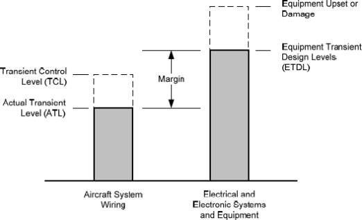
g. Establish equipment transient design levels (ETDLs) and aircraft actual transient levels (ATLs)
CS 23.1306/2515, 25.1316, 27.1316, and 29.1316 define the specifications in terms of functional effects that are performed by aircraft electrical and electronic systems. From a design point of view, lightning protection for systems is shared between protection incorporated into the aircraft structure and wiring, and protection incorporated into the equipment. Therefore, the requirement allocations for electrical and electronic system lightning protection can be based on the concept of ETDLs and ATLs.
1. The applicant should determine and specify the ETDLs for the electrical and electronic equipment that make up the systems to be assessed. The ETDLs set qualification test levels for the systems and equipment. They define the voltage and current amplitudes and waveforms that the systems and equipment must withstand without any adverse effects. The ETDLs for a specific system depend on the anticipated system and wiring installation locations on the aircraft, the expected shielding performance of the wire bundles and structure, and the system criticality.
2. The ATLs are the voltage and current amplitudes and waveforms actually generated on the aircraft wiring when the aircraft is exposed to lightning, as determined by aircraft test, analysis, or similarity. The difference between an ETDL and an ATL is the margin. Figure 1 shows the relationship between the ATL and the ETDL. The aircraft, interconnecting wiring, and equipment protection should be evaluated to determine the most effective combination of ATLs and ETDLs that will provide acceptable margin. Appropriate margins to account for uncertainties in the verification techniques may be necessary as mentioned in paragraph 7 of this AMC.
3. Typically, the applicant should specify the ETDLs prior to aircraft certification lightning tests or analyses to determine the aircraft ATLs. Therefore, the expected aircraft transients must be based upon results of lightning tests on existing aircraft, engineering analyses, or knowledgeable estimates. These expected aircraft lightning transient levels are termed transient control levels (TCLs)
Figure 1: Relationships between transient levels
h. Verify compliance with the applicable specifications
1. The applicant should demonstrate that the systems comply with the applicable specifications of CS 23.1306/2515, 25.1316, 27.1316, and 29.1316.
2. The applicant should demonstrate that the ETDLs exceed the ATLs by the margin established in their certification plan.
3. Verification may be accomplished by tests, analyses, or by demonstrating similarity to previously certified aircraft and systems. The certification process for Level A systems is contained in Section 7. The certification process for Level B and Level C systems is contained in Section 8.
4. The applicant should submit their compliance plan in the early stages of the programme to the Agency for review (see details in paragraph 7(a)). Experience shows that, particularly with aircraft using new technology or those that have complex systems, early agreement on the compliance plan benefits the certification of the product. The plan should define acceptable ways to resolve critical issues during the certification process. Analyses and test results during the certification process may warrant modifications to the design or verification methods. When significant changes are necessary, the certification plan should be updated accordingly.
i. Take corrective measures (if needed)
If tests and analyses show that the system did not meet the pass/fail criteria, review the aircraft, installation or system design and improve protection against lightning.
Figure 2: Routes to lightning compliance — Level A systems

(n) = Step number as described in Section 7 of this AMC
7. STEPS TO ‘LEVEL A’ SYSTEM LIGHTNING COMPLIANCE
Figure 2 illustrates a process that the applicant can use to demonstrate that their Level A system complies with CS 23.1306(a)/2515(a), 25.1316(a), 27.1316(a), and 29.1316(a).
a. Step 1 — Identify Level A systems
1. Level A systems should be identified as described in paragraph 6(c). The detailed system performance pass/fail criteria should be defined. The applicant should not begin testing or analysing their Level A system before the Agency has concurred on these criteria. Specific equipment, components, sensors, power systems and wiring associated with each Level A system should be identified in order to perform the ETDL verification mentioned in paragraphs 7(g) and 7(h).
2. The system defined for paragraph (a) of CS 23.1306/2515, 25.1316, 27.1316, and 29.1316 is not required to include:
(a) equipment, components or electrical interconnections required only for non-normal situations; or
(b) equipment, components or electrical interconnections required only for dispatching under master minimum equipment lists (MMELs) (when operational suitability data (OSD) is applicable).
3. Some systems include mechanical, hydraulic, and/or pneumatic channels as well as electrical and electronic channel(s) to perform functions whose failure would prevent continued safe flight and landing. The lightning safety assessment for CS 23.1306/2515(a), 25.1316(a), 27.1316(a), and 29.1316(a) only applies to functions performed by electrical and electronic systems. The lightning safety assessment should consider electrical or electronic failures that would adversely affect the function of the mechanical, hydraulic, and/or pneumatic channel(s). If electrical or electronic equipment and components, as well as electrical interconnections are used to assist, augment, or monitor for control loop feedback, the mechanical, hydraulic, and/or pneumatic channels in performing the normal operation of functions with potential failures that would prevent continued safe flight and landing, then the electrical and electronic channel(s) must comply with CS 23.1306/2515(a), 25.1316(a), 27.1316(a), and 29.1316(a).
4. CS 23.1306/2515(a), 25.1316(a), 27.1316(a), and 29.1316(a) do not require the applicant to assume pre-existing failure conditions when classifying the functional failure conditions and the scope of Level A systems. The applicant should consider total or partial loss of the systems and malfunctions of the systems, including hazardously misleading information presented to the flight crew during and after the aircraft is exposed to lightning.
5. CS 23.1306(a)(2), 25.1316(a)(2), 27.1316(a)(2), and 29.1316(a)(2) require that Level A systems automatically recover normal operation of the Level A functions in a timely manner after exposure to lightning. Automatic recovery applies to all redundant active channels of the Level A system required for normal operation unless its recovery conflicts with other operational or functional requirements of the system. The exception for automatic recovery conflicts must be based on aircraft operational or functional requirements independent of lightning exposure.
6. Appendix 2 Examples of lightning safety assessment considerations — Level A systems provides examples of systems’ scope based on the guidance above.
b. Step 2 — Define aircraft and system lightning protection. The applicant should define the lightning protection features to be incorporated into the aircraft and system designs, based on the lightning environments that are applicable to their aircraft and its Level A systems. Equipment, system, and aircraft lightning protection design may occur before aircraft-level tests are performed, and before the actual internal lightning environment is determined. Therefore, the equipment, system and aircraft lightning protection design should be based on an estimate of the expected internal lightning environment.
c. Step 3 — Establish the system’s ETDLs. The applicant should establish the aircraft system’s ETDLs from an evaluation of expected lightning transient amplitudes and waveforms for the system installation, structure and wiring configuration on a specific aircraft. ETDLs that exceed the ATLs by an acceptable margin should be established. In general, the ETDLs for equipment in a complex system will not be the same for all wire bundles connecting them to other equipment in the system. The applicant may use the results of lightning tests on existing similar aircraft, engineering analyses, or knowledgeable estimates to establish the appropriate system’s ETDLs. While specific aircraft configurations and system installations may lead to ETDLs that have amplitudes and waveforms different from those defined in EUROCAE ED-14G Section 22, ETDLs are often specified using the information from Section 22. The ETDLs must exceed the ATLs by an acceptable margin.
d. Step 4 — Select the ETDL verification method. The applicant should determine whether to perform system qualification tests on the Level A system, or whether to base the system verification on previous system qualification tests performed on a similar system.
e. Step 5 — Verify the system’s ETDLs using system qualification tests
1. Equipment test. Lightning induced transient susceptibility tests (Tolerance Damage and Functional Upset) of RTCA / DO-160G / EUROCAE ED-14G (or latest version) Section 22 may be used to build confidence in the equipment’s lightning immunity before conducting integrated system qualification tests. Equipment tests may be used to augment the system qualification tests where appropriate. For equipment whose lightning immunity is evaluated as part of the system qualification tests, the individual equipment’s lightning testing described in this step is optional.
2. The applicant should identify the equipment, components, sensors, power systems, and wiring associated with the Level A system undergoing ETDL verification tests, specifically considering the system functions whose failures would have catastrophic consequences. For complex Level A systems, the system configuration may include redundant equipment, multiple power sources, multiple sensors and actuators, and complex wire bundles. The applicant should define the system configuration used for the ETDL verification tests. The applicant should obtain the Agency’s acceptance of their system configuration for ETDL verification tests.
3. If the Level A System consists of multiple similar channels, the applicant can propose using one or more channels in the laboratory test set-up for the integrated system, instead of all similar channels. The applicant should demonstrate that the laboratory test set-up adequately performs the functions that must demonstrate compliance with CS 23.1306/2515(a), 25.1316(a), 27.1316(a), and 29.1316(a). The applicant should ensure that the laboratory test set-up represents and monitors any cross-channel interactions, such as cross-channel data links, redundancy management, and system health monitoring.
Note: Similar channels are composed of equipment that has the same hardware but not necessarily the same part number; if Pin Programming and/or Software are used to identify or configure equipment of similar channels, it must be assessed whether these differences have an impact on the functions performed.
4. The applicant should verify the ETDLs using single-stroke, multiple-stroke, and multiple-burst tests on the system wire bundles. The applicant should use waveform sets and test levels for the defined ETDLs, and demonstrate that the system operates within the defined pass/fail criteria during these tests. No equipment damage that adversely affects the function or system should occur during these system tests or during single-stroke pin injection tests using the defined ETDLs. It could be verified during system test that the equipment ETDL declared by the supplier is not exceeded. EUROCAE ED-14G Section 22 provides acceptable test procedures and waveform set definitions. In addition, EUROCAE ED-105A provides acceptable test methods for complex and integrated systems.
5. The applicant should evaluate any system effects observed during the qualification tests to ensure they do not adversely affect the system’s continued performance. The Level A system performance should be evaluated for functions whose failures or malfunctions would prevent the continued safe flight and landing of the aircraft. Other functions performed by the system whose failures or malfunctions would reduce the capability of the aircraft or the ability of the flight crew to respond to an adverse operating condition should be evaluated using the guidance provided in Section 10 of this AMC. The applicant should obtain the Agency’s acceptance of their evaluation.
f. Step 6 — Verify the system’s ETDLs using existing system data (similarity)
1. The applicant may base their ETDL verification on similarity to previously certified systems without performing more tests. This may be done when:
(a) there are only minor differences between the previously certified system and installation and the system and installation to be certified;
(b) there are no unresolved in-service system problems related to lightning strikes on the previously certified system; and
(c) the previously certified system ETDLs were verified by qualification tests.
2. To use similarity to previously certified systems, the applicant should assess the differences between the previously certified system and installation and the system and installation to be certified that can adversely affect the system’s susceptibility.
The assessment should cover the following:
(a) system interface circuits;
(b) wire size, routing, arrangement (parallel or twisted wires), connector types, wire shields, and shield terminations;
(c) lightning protection devices, such as transient suppressors and lightning arrestors;
(d) grounding and bonding; and
(e) system software and AEH.
3. If the applicant is unsure how the differences will affect the systems and installations, they should perform more tests and analyses to resolve the open issues.
4. The applicant should assess every system, even if it uses equipment and installation techniques that have a previous certification approval.
5. The use of similarity should not be used for a new aircraft design with new systems.
g. Step 7 — Select the aircraft verification method
1. Level A systems require an aircraft assessment. The aircraft assessment should determine the ATLs where Level A systems are installed in the aircraft. The applicant should choose whether to use aircraft tests or previous data from similar aircraft types (similarity). For level A display systems only, the applicant could select the ETDLs as proposed in Table 3.
2. If analysis is used to determine the ATLs, test data should be provided to support this analysis. Any analysis results should take into account the quality and accuracy of the analysis. Significant testing, including aircraft-level testing, may be required to support the analysis.
h. Step 8 — Determine the ATLs using aircraft tests. See SAE ARP 5415B / EUROCAE ED-158, User Manual for certification of aircraft Electrical and Electronic systems for the indirect effects of lightning, and EUROCAE ED‑105A Aircraft Lightning Test Method for guidance on how to determine the ATLs.
i. Step 9 — Determine the ATLs using analysis. See SAE ARP 5415B / EUROCAE ED-158 for guidance on how to analyse aircraft to determine the ATLs. Acceptance of the analysis method chosen will depend on the accuracy of the method. The applicant should confirm their analysis method accuracy using experimental data, and gain agreement of their analysis approach from the Agency.
j. Step 10 — Determine the ATLs using similarity
1. The use of similarity to determine the ATLs may be used when:
(a) there are only minor differences between the previously certified aircraft and system installation and the aircraft and system installation to be certified; and
(b) there is no unresolved in-service history of problems related to lightning strikes to the previously certified aircraft.
2. If significant differences are found that will affect the aircraft ATLs, the applicant should perform more tests and analyses to resolve the open issues.
3. To use similarity, the applicant should assess the aircraft, wiring, and system installation differences that can adversely affect the system’s susceptibility. When assessing a new installation, the applicant should consider the differences affecting the internal lightning environment of the aircraft and its effects on the system.
The assessment should cover the following:
(a) the aircraft type, equipment locations, airframe construction, structural materials, and apertures that could affect attenuation of the external lightning environment;
(b) the system wiring size, length, and routing; wire types (whether parallel or twisted wires), connectors, wire shields, and shield terminations;
(c) lightning protection devices, such as transient suppressors and lightning arrestors; and
(d) grounding and bonding.
4. Similarity cannot be used for a new aircraft design with new systems.
k. Step 11 — Determine the transient levels using RTCA / DO-160G / EUROCAE ED-14G, Section 22, Guidance for Level A displays only
1. The applicant may select ETDLs for their Level A display system using the guidance in this section, without specific aircraft test or analysis. Level A displays involve functions for which the pilot will be in the loop through pilot–system information exchanges. Level A display systems typically include the displays, symbol generators, data concentrators, sensors (such as attitude, air data, and heading sensors), interconnecting wiring, and the associated control panels.
2. This approach should not be used for other Level A systems, such as control systems, because failures and malfunctions of those systems can more directly and abruptly contribute to a catastrophic failure event than display system failures and malfunctions. Therefore, other Level A systems require a more rigorous lightning transient compliance verification programme.
3. The information in Table 3 should be used to evaluate aircraft and system installation features in order to select the appropriate ETDLs for the system. Table 3 defines test levels for ETDLs, based on EUROCAE ED-14G Section 22, Tables 22-2 and 22-3.
The applicant should provide the Agency with a description of their aircraft and display system installation features and compare these with the information in Table 3 to substantiate the ETDL selected for their aircraft and Level A display system installation. When selecting the ETDLs using the guidance provided in this step, an acceptable margin between the anticipated ATLs for display system installations is incorporated in the selected ETDLs.
Table 3: Equipment transient design levels — Level A displays
|
EUROCAE ED-14G Section 22 levels |
|
Level A display system installation location
|
|
|
||
|
|
||
|
|
||
|
|
|
|
|
Level 5 |
|
The applicant should use this level when the equipment under consideration, its associated wire bundles, or other components connected by wiring to the equipment are in aircraft areas exposed to very severe lightning transients. — areas with composite materials whose shielding is not very effective; — areas where there is no guarantee of structural bonding; and — other open areas where there is little shielding. The applicant can also use this level to cover a broad range of installations. The applicant may need higher ETDLs when there are high-current density regions on mixed conductivity structures (such as wing tips, engine nacelle fins, etc.) because the system wiring may divert some of the lightning current. If the applicant is the system designer, measures should be applied to reduce the need for higher ETDLs. |
|
|
||
|
|
||
|
|
||
|
|
|
|
|
Level 4 |
|
The applicant should describe how to verify compliance. Typically, the verification method chosen uses this level when the equipment under consideration, its associated wire bundles, or other components connected by wiring to the equipment are in aircraft areas exposed to severe lightning transients. These areas are defined as outside the fuselage (such as wings, fairings, wheel wells, pylons, control surfaces, etc.). |
|
|
||
|
|
||
|
|
||
|
|
||
|
|
||
|
|
|
|
|
Level 3
|
|
The applicant should use this level when the equipment under consideration, its associated wire bundles, and other components connected by wiring to the equipment are entirely in aircraft areas with moderate lightning transients. These areas are defined as the inside metal aircraft structure or composite aircraft structure whose shielding is as effective as metal aircraft structure, and without additional measures to reduce lightning coupling to wires. Examples of such areas are avionics bays not enclosed by bulkheads, cockpit areas, and locations with large apertures (that is, doors without electromagnetic interference (EMI) gaskets, windows, access panels, etc.). Current-carrying conductors in these areas (such as hydraulic tubing, control cables, wire bundles, metal wire trays, etc.) are not necessarily electrically grounded at bulkheads. When few wires exit the areas, applicants should either use a higher level (that is, Level 4 or 5) for these wires or offer more protection for these wires. |
|
|
||
|
|
||
|
|
||
|
|
|
|
|
Level 2
|
|
The applicant should use this level when the equipment under consideration, its associated wire bundles, and other components connected by wiring to the equipment are entirely in partially protected areas. These areas are defined as the inside of a metallic or composite aircraft structure whose shielding is as effective as metal aircraft structure, if the applicant takes additional measures to reduce the lightning coupling to wires. Wire bundles in these areas pass through bulkheads and have shields that end at the bulkhead connector. When a few wires exit these areas, the applicant should use either a higher level (that is, Level 3 or 4) or provide more protection for these wires. The applicant should install wire bundles close to the ground plane to take advantage of other inherent shielding from metallic structures. Current-carrying conductors (such as hydraulic tubing, control cables, metal wire trays, etc.) are electrically grounded at all bulkheads. |
|
|
|
|
|
Level 1
|
|
The applicant should use this level when the equipment under consideration, its associated wire bundles, and other components connected by wiring to the equipment are entirely in well-protected aircraft areas. These areas are defined as electromagnetically enclosed. |
|
|
||
|
|
|
|
l. Step 12 — Verify compliance with the applicable requirements
The applicant should compare the verified system ETDLs with the aircraft ATLs and determine whether an acceptable margin exists between the ETDLs and the ATLs. Margins account for uncertainty in the verification method. As confidence in the verification method increases, the margin can decrease. An ETDL exceeding the ATL by a factor of two is an acceptable margin for Level A systems, if this margin is verified by aircraft test or by analysis supported by aircraft-level tests. For Level A display systems where the ETDLs are determined using the guidance provided in Table 3, an acceptable margin is already incorporated in the selected ETDLs. For other verification methods, the margin should be agreed upon with the Agency.
m. Step 13 — Corrective measures
1. When a system fails to meet the certification requirements, corrective actions should be selected. Any changes or modifications made to the aircraft, system installation or the equipment may require more testing and analysis.
2. To meet the certification requirements, the applicant may need to repeat system qualification testing, or aircraft-level testing and analysis (in whole or in part). This may include modification to the system or installation to obtain certification. The applicant should review these changes or modifications with the Agency to determine whether they are significant. If these changes or modifications are significant, the applicant should update their lightning certification plan accordingly. The updated certification plan shall be resubmitted to the Agency in accordance with point 21.A.15(c) for acceptance.
Figure 3: Routes to lightning compliance — Level B and Level C systems
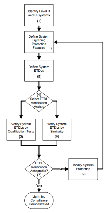
(n) = Step number as described in Section 9 of this AMC
8. STEPS TO ‘LEVEL B’ AND ‘LEVEL C’ SYSTEM LIGHTNING COMPLIANCE
Figure 3 illustrates a process that the applicant can use to demonstrate that their Level B and Level C systems comply with CS 23.1306(b)/2515(b), 25.1316(b), 27.1316(b), and 29.1316(b).
a. Step 1 — Identify Level B and Level C systems
1. The applicant should identify their Level B and Level C systems as described in paragraph 6(c).
2. The applicant should define the detailed system performance pass/fail criteria. The applicant should obtain the Agency’s concurrence on this criterion before starting tests or analyses of Level B and C systems.
b. Step 2 — Define system lightning protection. The applicant should define the lightning protection features incorporated into the system designs applicable to Level B and Level C systems. The design of equipment and system lightning protection may occur before aircraft-level tests are performed, and before the actual internal lightning environment is determined. Therefore, the equipment system lightning protection design should be based on an estimate of the expected internal lightning environment.
c. Step 3 — Establish the ETDLs
1. The applicant may use the ATLs determined during aircraft-level tests or analyses performed for Level A systems to establish the appropriate ETDLs for Level B and Level C systems.
2. Alternatively, the applicant may use the definitions in EUROCAE ED-14G Section 22 to select the appropriate ETDLs for their Level B and Level C systems. The following should be considered when selecting an appropriate level:
(a) The applicant can use EUROCAE ED-14G Section 22 Level 3 for most Level B systems.
(b) For Level B systems and the associated wiring installed in aircraft areas with more severe lightning transients, the applicant can use EUROCAE ED-14G
Section 22 Level 4 or 5, as appropriate to the environment. Examples of aircraft areas with more severe lightning transients are those external to the fuselage, areas with composite structures showing poor shielding effectiveness, and other open areas.
(c) The applicant should use EUROCAE ED-14G Section 22 Level 2 for most Level C systems.
(d) For Level C systems installed in aircraft areas with more severe lightning transients, the applicant should use EUROCAE ED-14G Section 22 Level 3. Examples of aircraft areas with more severe lightning transients are those external to the fuselage, areas with composite structures showing poor shielding effectiveness, and other open areas.
(e) The applicant should provide the Agency with a description of their aircraft and system installation features to substantiate the EUROCAE ED-14G Section 22 levels selected for their system.
d. Step 4 — Select the ETDL verification method. The applicant should determine whether they will perform equipment lightning tests on the Level B and Level C systems, or whether they will base the compliance on previous equipment tests performed for a similar system.
e. Step 5 — Verify the system’s ETDL using equipment qualification tests
1. Equipment qualification tests should be performed using the selected test levels and single-stroke, multiple-stroke, and multiple-burst waveform sets. It should be demonstrated that the equipment operates within the defined pass/fail criteria during these tests. No equipment damage should occur during these equipment qualification tests or during single-stroke pin injection tests using the defined ETDLs. EUROCAE ED-14G Section 22 provides acceptable test procedures and waveform set definitions.
2. Any equipment effects observed during the qualification tests should be evaluated to ensure that they do not adversely affect the system’s continued performance. The applicant should obtain the Agency’s acceptance of their evaluation.
3. Multiple-stroke and multiple-burst testing is not required if an analysis shows that the equipment is not susceptible to upsets, or that the equipment may be susceptible to upsets but a reset capability exists so that the system recovers in a timely manner.
f. Step 6 — Verify the system’s ETDL using existing equipment data (similarity)
1. ETDLs may be verified by similarity to previously certified systems without performing more tests. The applicant may do this when:
(a) there are only minor differences between the previously certified system and installation and the system and installation to be certified;
(b) there are no unresolved in-service system problems related to lightning strikes on the previously certified system; and
(c) the previously certified system ETDLs were verified by qualification tests.
2. The assessment should cover the following:
(a) equipment interface circuits;
(b) the wire sizes, routing, arrangement (parallel or twisted wires), connector types, wire shields, and shield terminations;
(c) lightning protection devices, such as transient suppressors and lightning arrestors;
(d) grounding and bonding; and
(e) equipment software, firmware, and hardware.
3. If significant differences are found that will affect the systems and installations, the applicant should perform more tests and analyses to resolve the open issues.
g. Step 7 — Verify compliance with the applicable requirements
The applicant should demonstrate that the Level B and Level C systems meet their defined acceptance criteria during the qualification tests at the selected system ETDLs.
h. Step 8 — Corrective measures
When a system fails to meet the certification requirements, the applicant should decide on corrective actions. If the system or installation is changed or modified, the equipment qualification testing may need to be repeated. The applicant should review these changes or modifications with the Agency to determine whether they are significant. If these changes or modifications are significant, the applicant should update their lightning certification plan accordingly. The updated certification plan shall be resubmitted in accordance with point 21.A.15(c) to the Agency for acceptance.
9. LIGHTNING COMPLIANCE DEMONSTRATION
a. Lightning compliance plan. An overall lightning compliance plan should be established to clearly identify and define lightning certification specifications, lightning protection development, and the design, test, and analysis activities intended to be part of the compliance effort. This plan should provide definitions of the aircraft systems, installations, and protective features against which lightning compliance will be assessed. The lightning compliance plan should be discussed with, and submitted to, the Agency for acceptance before initiating lightning compliance activities. If the aircraft, system, or installation design changes after approval, a revised lightning compliance plan should be submitted to the Agency for acceptance. The lightning compliance plan should include the following:
1. a lightning compliance plan summary;
2. identification of the aircraft systems, with their classifications based on the safety assessment as it relates to lightning (see paragraph 6(c)(2));
3. the planned or expected lightning environment for installed systems; and
4. the verification methods, such as test, analysis, or similarity.
b. Methods of compliance verification
1. Various methods are available to aid in demonstrating lightning compliance. Methods acceptable to the Agency are described in Sections 7 and 8 of this AMC. Figure 2 above outlines the steps to lightning compliance for systems requiring Level A lightning certification. Figure 3 above outlines the steps to lightning compliance for systems requiring Level B or Level C lightning certification. The steps in these figures are not necessarily accomplished sequentially. Wherever a decision point is indicated on these figures, the applicant should complete the steps in that path as described in Sections 7 and 8 of this AMC.
2. Other lightning compliance techniques may be used to demonstrate system performance in the lightning environment; however, those techniques should be accepted by the Agency before using them.
c. Lightning verification test, analysis, or similarity plan. Test, analysis and similarity are all acceptable methods. The applicant must choose the method or the combination of methods most appropriate for their project. See Sections 7 and 8 of this AMC, and SAE ARP 5415B / EUROCAE ED-158 for additional guidance for selecting the appropriate method. Specific lightning test, analysis, or similarity plans could be prepared to describe specific verification activities. A single verification plan combining various methods for all the selected systems or dedicated verification plans may be necessary. For example, there may be several systems or equipment laboratory test plans, an aircraft test plan, or a similarity plan for selected systems on an aircraft.
1. Test plan
(a) A lightning compliance test plan may include the equipment, system, and aircraft test objectives for the acquisition of data to support lightning compliance verification. The plan should provide an overview of the factors to be addressed for each system test specification. The test plan should include the following:
(1) the purpose of the test;
(2) a description of the aircraft and/or the system to be tested;
(3) system configuration drawings;
(4) the proposed test set-up and methods;
(5) the intended test levels;
(6) pass/fail criteria; and
(7) the test schedule and test location.
(b) The test plan should cover Level A, B, and C systems and equipment, as appropriate. Level A systems may require both systems qualification laboratory tests and aircraft tests. Level B and Level C systems and equipment require only equipment qualification laboratory testing.
(c) The test plan should describe the appropriate aspects of the systems to be tested and their installation. Additionally, the test plan should reflect the results of any analysis performed in the overall process of the lightning compliance evaluation.
2. Analysis plan. A lightning compliance analysis plan should include the objectives, at both system and equipment level, for generating data to support lightning compliance verification. Comprehensive modelling and analysis for voltage and current transients to aircraft systems and structures is an emerging technology; therefore, the analysis plan should be coordinated with the Agency to determine an acceptable scope for the analysis. The analysis plan should include the following:
(a) the purpose and scope of the analysis;
(b) a description of the aircraft and/or the system addressed by the analysis;
(c) system configuration descriptions;
(d) the proposed analysis methods;
(e) the approach for validating the analysis results; and
(f) pass/fail criteria, including margins to account for analysis uncertainty.
3. Similarity plan. A similarity plan should describe the approach undertaken to use the certification data from previously certified systems, equipment, and aircraft in the proposed lightning compliance programme. The similarity plan should include the following:
(a) the purpose and scope of the similarity assessment;
(b) the specific systems addressed by the similarity assessment;
(c) the data used from previously certified systems, equipment, and aircraft;
(d) details on significant differences between the aircraft and the system to be certified and the similar aircraft and the system from which the data will be used; and
(e) when data has limited substantiation, a description and justification for margins to account for similarity uncertainty.
d. Compliance reports. One or more compliance reports may be necessary to document the results of the test, analysis, or similarity assessments. For new or significantly modified aircraft, lightning compliance reports may include many system and equipment test reports, aircraft test reports, and lightning vulnerability analysis reports. For these types of lightning certification programmes, a compliance summary report may be useful to summarise the results of tests and analyses. For lightning certification programmes of relatively simple systems, a single compliance report is adequate.
1. Test reports. Comprehensive test reports should be produced at the conclusion of lightning compliance testing. The test reports should include descriptions of the salient aspects of equipment or system performance during the test, details of any area of non-compliance with lightning requirements, actions taken to correct the non-compliance, and any similarity declarations. The applicant should also provide the supporting rationale behind any deviations from the system performance observed during testing.
2. Analysis reports. Analysis reports should describe the details of the analytical model, the methods used to perform the analysis, and the results of the analysis. The reports should identify any modelling uncertainty and justify the margins established in the analysis plan.
3. Similarity reports. Similarity reports should document the significant aircraft, system, equipment, and installation features that are common between the aircraft or system that is the subject of the similarity analysis and the aircraft or system that was previously certified for lightning. The applicant should identify all the significant differences encountered, along with the assessment of the impact of these differences on lightning compliance. These reports should also justify the margins established in the similarity plan.
10. MAINTENANCE, PROTECTION ASSURANCE, AND MODIFICATIONS
a. The minimum maintenance required to support lightning certification should be identified in the instructions for continued airworthiness (ICAs) as specified in CS 23.1529/2625, 25.1529, 25.1729, 27.1529, and 29.1529, as appropriate. Dedicated devices or specific features may be required to provide lightning protection for the installation of a system or equipment. Appropriate maintenance procedures should be defined for these devices and features to ensure in-service protection integrity. A lightning protection assurance programme should be proposed in the certification plan to identify all actions necessary to justify or to verify that the maintenance procedures are adequate. This assurance programme may propose a surveillance programme based on a sampling of the fleet for monitoring the effectiveness of the protection features and/or maintenance procedures. See SAE ARP 5415B / EUROCAE ED-158 for more information on these topics.
b. The maintenance procedures should consider the effects of corrosion, fretting, flexing cycles, or other causes that could degrade these lightning protection devices. Whenever applicable, specific replacement times of these devices and features should be identified.
c. Aircraft or system modifications should be assessed for the impact that any changes will have on the lightning protection. This assessment should be based on analysis and/or measurement.
[Amdt 20/23]
Appendix 1 to AMC 20-136A — Definitions and acronyms
ED Decision 2022/001/R
a. Definitions
Adverse effect: a response of a system that results in an unexpected and unacceptable operation of an aircraft system, or unexpected and unacceptable operation of the function performed by the system.
Actual transient level (ATL): the level of transient voltage or transient current that appears at the equipment interface circuits because of the external environment. This level may be less than or equal to the transient control level but should not be greater.
Aperture: an electromagnetically transparent opening.
Attachment point: a point where the lightning flash contacts the aircraft.
Automatically recover: return to normal operations without pilot action.
Channel: a subset of a system consisting of equipment, components, elements and electrical interconnections, which performs an aircraft function provided by the system. A system could be composed of redundant similar or dissimilar channels in order to maintain the function at aircraft level in case of failure on one or several channels.
Component damage: a condition in which transients permanently alter the electrical characteristics of a circuit. Because of this, the component can no longer perform to its specifications.
Continued safe flight and landing: the capability for continued controlled flight and landing at a suitable location, possibly using emergency procedures, but without requiring exceptional piloting skill or strength. For CS-25 aeroplanes, the pilot must be able to land safely at a suitable airport. For CS-23 aeroplanes, it is not necessary to land at an airport. For rotorcraft, the rotorcraft must continue to cope with adverse operating conditions, and the pilot must be able to land safely at a suitable site. Some aircraft damage may be associated with a failure condition during flight or upon landing.
Direct effects: physical damage to the aircraft or to its electrical and electronic systems. Direct attachment of lightning to the system’s hardware or components causes the damage. Examples of direct effects include tearing, bending, burning, vaporisation, or blasting of aircraft surfaces and structures, and damage to the electrical and electronic systems.
Electrical and electronic system: an electrical or electronic system includes all electrical and electronic equipment, components, elements, and the electrical interconnections that are required to perform a particular function.
Equipment: a component of an electrical or electronic system with interconnecting electrical conductors.
Equipment electrical interface: a location on a piece of equipment where an electrical connection is made to the other equipment in a system of which it is a part. The electrical interface may consist of individual wires or wire bundles that connect the equipment.
Equipment transient design level (ETDL): the peak amplitude of transients to which equipment is qualified.
External environment: the natural lightning environment, outside the aircraft, for design and certification purposes. See SAE ARP 5412B / EUROCAE ED-84A, which references documents that provide additional guidance on aircraft lightning environments and the related waveforms.
Immunity: the capacity of a system or piece of equipment to continue to perform its intended function, in an acceptable manner, in the presence of RF fields.
Indirect effects: electrical transients induced by lightning in aircraft electrical or electronic circuits.
Internal environment: the electric and magnetic fields, currents, and voltages on and within the aircraft produced by a lightning strike to the aircraft.
Lightning flash: the total lightning event. It may occur in a cloud, between clouds, or between a cloud and the ground. It can consist of one or more return strokes, plus intermediate or continuing currents.
Lightning strike: attachment of the lightning flash to the aircraft.
Lightning strike zones: aircraft surface areas and structures that are susceptible to lightning attachment, dwell times, and current conduction. See SAE ARP 5414B / EUROCAE ED-91A, which references documents that provide additional guidance on aircraft lightning zoning.
Lightning stroke (return stroke): a lightning current surge that occurs when the lightning leader (the initial current charge) makes contact with the ground or another charge centre. A charge centre is an area of high potential of opposite charge.
Margin: the difference between the equipment transient design levels and the actual transient level.
Multiple burst: a randomly spaced series of bursts of short duration, low-amplitude current pulses, with each pulse characterised by rapidly changing currents. These bursts may result as the lightning leader progresses or branches, and are associated with the cloud-to-cloud and intra-cloud flashes. The multiple bursts appear most intense when the initial leader attaches to the aircraft. See SAE ARP 5412B / EUROCAE ED-84A.
Multiple stroke: two or more lightning return strokes during a single lightning flash. See SAE ARP 5412B / EUROCAE ED-84A.
Non-normal situation: any situation that requires non-normal, abnormal, emergency, or unusual procedures, or configurations for operating an aircraft.
Normal operation: a status where the system is performing its intended function. When addressing compliance with CS 23.1306/2515(a)(2), 25.1316(a)(2), 27.1316(a)(2), and 29.1316(a)(2), the function whose failure would prevent the continued safe flight and landing should be in the same undisturbed state as before exposure to the lightning threat while other functions, performed by the same system, subject to CS 23.1306/2515(b), 25.1316(b), 27.1316(b), and 29.1316(b), are not required to be recovered. The system that performs the function may be nevertheless in a different state as long as the function is not adversely affected.
Timely manner: timely recovery has been introduced to account for the necessary period for complex systems to reconfigure safely after a disruption. The meaning of ‘in a timely manner’ depends upon the function performed by the system to be evaluated, the specific system design, interaction between that system and other systems, and interaction between the system and the flight crew, or the phase of flight, which must be considered in the safety assessment. Therefore, the definition of ‘in a timely manner’ must be determined for each specific function performed by the system. The applicable definition could be included in the lightning compliance plan for review and concurred with the Agency.
Transient control level (TCL): the maximum allowable level of transients that appear at the equipment interface circuits because of the defined external environment.
Upset: impairment, either permanent or momentary, of the system’s operation. For example, a change of digital or analogue state that may or may not require a manual reset.
b. Acronyms
|
14 CFR: |
Title 14 of the Code of Federal Regulations |
|
AC: |
advisory circular |
|
AMC: |
acceptable means of compliance |
|
ARP: |
aerospace recommended practice |
|
ATL: |
actual transient level |
|
CS: |
certification specification |
|
DAL: |
development assurance level (ED-79A / ARP 4754A) / |
|
DEL: |
direct effect of lightning |
|
ETDL: |
equipment transient design level |
|
EASA: |
European Union Aviation Safety Agency |
|
EUROCAE: |
European Organisation for Civil Aviation Equipment |
|
FAA: |
Federal Aviation Administration |
|
ICAs: |
instructions for continued airworthiness |
|
IEL: |
indirect effect of lightning |
|
TCL: |
transient control level |
[Amdt 20/23]
Appendix 2 to AMC 20-136A — Examples of lightning safety assessment considerations — Level A systems on large aeroplanes
ED Decision 2022/001/R
a. Establishing appropriate pass/fail criteria for complying with CS 25.1316(a) could only be achieved through a comprehensive review of the system design using an acceptable lightning functional hazard assessment process. The following paragraphs summarise approaches whereby pass/fail criteria for compliance with CS 25.1316(a) could be specified on the merit of specific system architecture attributes.
b. For the purposes of discussion and evaluation of the examples, the architectural strategies used in the system implementation need to be defined. Therefore, the additional definitions below should be considered:
(1) similar redundant channels: the multiple channels consist of equipment, components, electrical interconnections and configurations that are similar, typically with equipment that has identical part numbers. The channels should be independent. They may be configured in active, active‑backup, or passive-backup modes.
(2) dissimilar redundant channels: each channel is unique and independent of the others. They may be configured in active, active-backup, and passive-backup modes.
(3) combination of similar and dissimilar redundant channels: the combination of similar and dissimilar channels, as defined above, with independence between channels. They may be configured in active, active-backup, and passive-backup modes.
Notes:
(1) Active mode means the channel performs the aircraft function in normal operation.
(2) Active-backup mode means the channel is operational but not used to perform the aircraft function until switched to active mode either automatically or by flight crew action.
(3) Passive-backup mode means the channel is not operational; switching to active mode is either automatic or by flight crew action upon failure recognition.
(4) Combination of electrical/electronic and mechanical, hydraulic and/or pneumatic channels: certain architectures combine electrical and electronic channels with mechanical, hydraulic and/or pneumatic channels. These combinations of electrical/electronic and mechanical, hydraulic or pneumatic channels may be configured in active, active-backup, and passive-backup modes.
(5) These examples are theoretical and intended to facilitate a discussion from which universal guidelines may be derived to help develop useful guidance material. It is not the intention to account for all possible configurations, but only to represent the common system architectures or some that present unique challenges.
c. This Appendix presents examples of large aeroplane systems with multiple independent and redundant channels performing a function whose failure would prevent continued safe flight and landing.
These examples could also be used for other types of aircraft.
|
Example 1 |
|||
|
Function |
25.1316(a) System |
||
|
Channel |
Channel |
Channel |
|
|
Display of attitude, altitude, and airspeed information to the pilots during IFR operations (e.g. primary display system and associated sensors, with dissimilar standby display system and sensors) |
Active
(Pilot displays and associated sensors) |
Active
(Co-pilot displays and associated sensors) |
Active-backup
(Dissimilar standby display and associated sensors) |
|
Requirements for compliance demonstration (CS 25.1316) |
(a)(1), (a)(2) |
(a)(1), (a)(2) |
(b) |
|
Discussion: This example depicts the requirement of CS 25.1333 for independent displays of information essential to the safety of flight at each pilot station. The standby display is required in order to achieve the safety objectives of CS 25.1309. Either the pilot or the co-pilot can be the pilot flying (PF) or pilot monitoring (PM) during normal operations, so both the pilot and co-pilot display systems should be considered as active systems. Compliance with CS 25.1316(a)(1) and (a)(2) should demonstrate that neither pilot display of aircraft attitude, altitude, and airspeed is adversely affected and that each of them recovers normal operation of these Level A functions when the aircraft is exposed to lightning. It is acceptable that the dissimilar standby display demonstrates compliance with the CS 25.1316(b) requirements with LCL B. The adverse effects must include both a loss of, and hazardously misleading, attitude, altitude, and airspeed information. |
|||
|
Example 2 |
|||
|
Function |
25.1316(a) System |
||
|
Channel |
Channel |
Channel |
|
|
Full authority control of pitch, yaw, and roll using electrical and electronic flight control systems |
Active or active‑backup
(Flight control system #1) |
Active or active‑backup
(Flight control system #2) |
Active or active‑backup
(Flight control System #3) |
|
Requirements for compliance demonstration (CS 25.1316) |
(a)(1), (a)(2) |
(a)(1), (a)(2) |
(a)(1), (a)(2) |
|
Discussion: This example depicts an electronic flight control system comprising three independent channels to meet the safety objectives of CS 25.1309. At any time, any one of the three channels can operate as the active channel. Only one channel operates in an active mode while the others are in active-backup mode. Any channel can perform the control function at any time; therefore, all the channels must comply with CS 25.1316(a)(1) and (a)(2). |
|||
|
Example 3 |
|||
|
Function |
25.1316(a) System |
||
|
Channel |
Channel |
Channel |
|
|
Provide engine overspeed protection
|
Active (Electronic engine control system)
(Normal speed control) |
Active or active‑backup (Electronic engine control system)
(Overspeed protection) |
Active (Independent mechanical overspeed protection) |
|
Requirements for compliance demonstration (CS 25.1316) |
(b) |
(b) |
Not subject to |
|
Discussion: This example depicts the function of engine overspeed protection performed by a combination of active electrical and electronic control and mechanical system control. The mechanical channel must provide overspeed protection during normal operations, and be independent of the active electronic control channels. The mechanical channel must not rely on electrical or electronic components to assist, augment, or monitor the overspeed protection. If the mechanical channel is independent of the electronic engine control speed control and overspeed protection, and has no electrical or electronic components that have failure modes that could prevent overspeed protection, then the engine overspeed protection function is not adversely affected when the aircraft is exposed to lightning. The system is, therefore, not subject to CS 25.1316(a). The electronic engine control channels should comply with CS 25.1316(b) with LCL B. This example only considers the overspeed protection feature implemented by the system. Other functions whose failure may be classified as catastrophic, like the loss of thrust control function where the function may be implemented by electronic control channels, should comply with CS 25.1316(a). |
|||
|
Example 4 |
|||
|
Function |
25.1316(a) System |
||
|
Channel |
Channel |
Channel |
|
|
Provide electrical power for electrical and electronic systems including those with catastrophic failure conditions
|
Active
(Left engine generator system) |
Active
(Right engine generator system) |
Passive-Backup
(Emergency power supply system driven by a ram-air turbine) |
|
Requirements for compliance demonstration (CS 25.1316) |
(a)(1), (a)(2) |
(a)(1), (a)(2) |
(b) |
|
Discussion: This example depicts a typical transport category aircraft electrical system on a twin-engined aircraft where two or more independent sources of electrical power are required by CS 25.1307(b) and a ram-air turbine is necessary to meet the safety objectives of CS 25.1309 and CS 25.1351(d). For this example, the electrical system consists of two active channels provided by a single main engine-driven generator on each engine with the associated distribution and controls, and a third passive-backup channel provided by a ram-air turbine electrical power system. The ram-air turbine electrical power system is stowed during normal operation and deployed either automatically and/or manually when power from the two main engine-driven generators is lost. The active engine generator system channels must not be adversely affected when the aircraft is exposed to lightning, and comply with CS 25.1316(a)(1) and (a)(2). The passive-backup ram-air turbine electrical power system does not mitigate adverse effects for compliance with CS 25.1316(a). It is acceptable that the ram-air turbine electrical power system demonstrates compliance with the CS 25.1316(b) specifications with LCL B. |
|||
|
Example 5 |
||||
|
Function |
25.1316(a) System |
|||
|
Channel |
Channel |
Channel |
Channel |
|
|
Provide electrical power for electrical and electronic systems including those with catastrophic failure conditions
|
Active
(Left engine generator system) |
Active
(Right engine generator system) |
Active (APU-driven generator system required for ETOPS flight beyond 180')
|
Passive-backup
(Emergency power supply driven by a |
|
Requirements for compliance demonstration (CS 25.1316) |
(a)(1), (a)(2) |
(a)(1), (a)(2) |
(a)(1), (a)(2) |
(b) |
|
Discussion: This example depicts a twin-engined transport category aircraft electrical system where two or more independent sources of electrical power are required by CS 25.1307(b), and an alternate source (driven by a ram-air turbine) is necessary to meet the safety objectives of CS 25.1309 and CS 25.1351(d). This configuration includes a third electrical power source driven by an auxiliary power unit (APU). This third source is required (active channel) for ETOPS beyond 180 minutes. As in Example 4, the emergency power source is a passive-backup channel provided by a ram-air turbine that remains stowed during normal flight and is deployed either automatically and/or manually when power from all other channels is lost. All active electrical power generation channels should comply with CS 25.1316(a)(1) and (a)(2). The passive‑backup electrical power generation channel does not mitigate the adverse effects due to lightning exposure to meet the intent of the lightning requirement. It is acceptable that the passive-backup channel demonstrates compliance with the CS 25.1316(b) requirements with LCL B. Note: For non-ETOPS or for ETOPS up to 180' aircraft, the APU LCL should be defined based on the specific aircraft safety assessment. |
||||
|
Example 6 |
||||
|
Function |
25.1316(a) System |
25.1316 System |
25.1316 System |
System |
|
Channel |
Channel |
Channel |
Channel |
|
|
Reduce aircraft speed on ground in a controlled manner using thrust reverser control system, spoiler deployment system, wheel braking system |
Active
Main brake system |
Active
(Electronic engine thrust reverse control with associated sensors) |
Active
(Electronic spoiler deployment control with associated sensors) |
Active
(Independent mechanical wheel braking) |
|
Requirements for compliance demonstration (CS 25.1316) |
(a)(1), (a)(2)
|
25.1316(a) or (b) depending on specific aircraft safety assessment |
25.1316(a) or (b) depending on specific aircraft safety assessment |
Not subject to CS 25.1316 |
|
Discussion: This example depicts an aircraft-level function that is performed by a combination of independent systems each contributing in part to the function during a specific phase of flight. In this case, each system implements very distinct aircraft-level functions that serve in a complementary manner to decelerate the aircraft during the landing roll. The mechanical wheel braking system is assumed to be independent of the other channels, with no associated electrical or electronic equipment to assist, augment, or monitor the mechanical wheel braking system. In this example, it is assumed that the main brake system includes failure conditions that are catastrophic. For the electronic engine thrust reverser control and the electronic spoiler control systems, the applicable parts of CS 25.1316 would depend on the specific failure conditions. The effectiveness, authority, and malfunctions associated with each system should be considered. Additionally, the interaction between the systems has also to be considered. Issues such as asymmetrical thrust reverser activation or spoiler deployment could adversely affect the main brake and mechanical wheel braking functions and could affect the safety classification for the thrust reverser and spoiler controls. An aircraft safety assessment must be carried out for each of these systems performing a specific aircraft-level function to identify and classify their failure conditions. The failure hazard classifications and the decomposition of each system into the constituent channels would then dictate which paragraphs of CS 25.1316 are needed. |
||||
|
Example 7 |
|||
|
Function |
25.1316(a) System |
||
|
Channel |
Channel |
Channel |
|
|
Provide altitude information to be displayed in IFR flight, using air-data computer connected to the primary flight display (PFD), and pneumatic standby instrument with alternate static port |
Active
(Air-data computer 1 with static port) |
Active
(Air-data computer 2 with static port) |
Active-Backup
(Pneumatic standby altimeter with alternate static port) |
|
Requirements for compliance demonstration (CS 25.1316) |
(a)(1), (a)(2) |
(a)(1), (a)(2) |
Not subject to |
|
Discussion: This example depicts the function to provide altitude information in IFR. The main sources are two air-data computers (ADCs) coupled to static ports and a backup source from a standby pneumatic altimeter coupled to an alternate static port independent from the main static ports. In such a case, the standby altimeter does not mitigate compliance with CS 25.1316(a) for the active ADC channels. The standby altimeter does not mitigate the common hazardously misleading altitude information from the active ADC channels for compliance with CS 25.1316(a). |
|||
|
Example 8 |
|||
|
Function |
25.1316(a) System |
||
|
Channel |
Channel |
Channel |
|
|
Control and protection of the aircraft pneumatic (bleed) system
(Top-level failure condition classification: catastrophic) |
Active
(Pneumatic system controller #1)
FDAL B / IDAL B
|
Active
(Pneumatic system controller #2)
FDAL B / IDAL B |
Passive-backup
(High pressure switch + valve)
FDAL C / IDAL C |
|
Requirements for compliance demonstration (CS 25.1316) |
(a)(1), (a)(2)
|
(a)(1), (a)(2) |
(b) |
|
Discussion: This is a generic example with the objective to show that it is not uncommon for the LCL of a given system to be different from the functional development assurance level (FDAL) and item development assurance level (IDAL), defined according to SAE ARP 4754A / EUROCAE ED-79A Guidelines for Development of Civil Aircraft and Systems. Therefore, it is important to use the proper nomenclature and avoid using the SAE ARP 4754A / EUROCAE ED-79A DAL or similar terms when referring to the LCL. In this example, the pneumatic control system is composed of two main active controllers and a simpler passive-backup channel that can perform the function, preventing the catastrophic event from occurring in case of failure of both controllers. The FDAL for each channel or member (SAE ARP 4754A / EUROCAE ED-79A nomenclature) was defined for a catastrophic top-level failure condition based on the ‘Option 2’ column 4 of Table 3 DEVELOPMENT ASSURANCE LEVEL ASSIGNMENT TO MEMBERS OF A FUNCTIONAL FAILURE SET of SAE ARP 4754A / EUROCAE ED-79A, which allows the combination of FDALs B+B+C for independent channels. In contrast, the respective LCLs would be A+A+B. Considering that lightning can simultaneously affect all channels, the considerations used for the IDAL assignment cannot be used, and compliance with CS 25.1316(a) is required for both the active channels performing a function with the catastrophic top-level failure condition. In this example, the IDAL for the passive-backup channel may be C. However, for lightning, the applicable part of CS 25.1316 is (b), similarly to Example 5. |
|||
[Amdt 20/23]